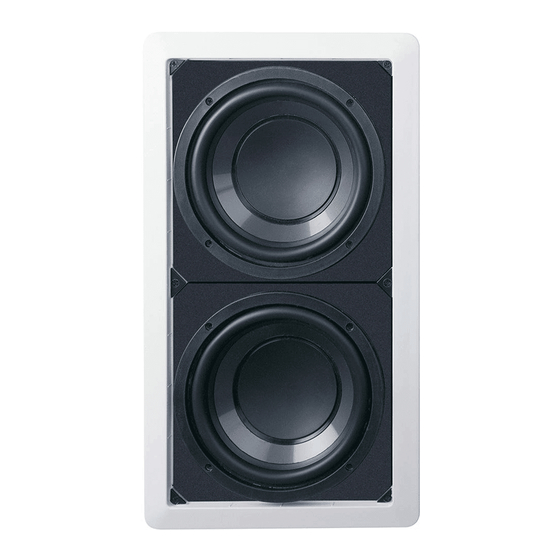
Atlantic Technology IWTS-8 SUB Instrucciones de instalación - Página 2
Navegue en línea o descargue pdf Instrucciones de instalación para Amplificador Atlantic Technology IWTS-8 SUB. Atlantic Technology IWTS-8 SUB 2 páginas. Woofer module
También para Atlantic Technology IWTS-8 SUB: Manual de instrucciones (16 páginas)

InWall Enclosure/Woofer Module Installation
The woofer assembly is very heavy. Use care and caution when han-
dling it and mounting it in the in-wall enclosure.
1
Before attempting to mount the woofer module you must first
apply the supplied 3/4 inch self-adhesive foam sealing gasket
to the rear side of the 8 SUB trim ring (Fig. ?). Remove the 8
SUB assembly from its box and place it face down on a flat
surface, being careful not to let anything damage the drivers.
2
Begin applying the foam gasket by peeling back approximately
2 inches of the adhesive's protective paper cover. Starting in
the middle of one side of the back of the trim ring apply the
adhesive side to the trim ring being careful to keep the foam
at least 1/8 inch away from the outside edge. Continue apply-
ing the gasket around the trim ring by stripping away the pro-
tective paper and pressing the adhesive side of the foam
against the trim ring. At the corners simply continue around
the trim (do not cut the foam in any corner) being careful not
to let the foam bunch up enough to hold the frame off the
wall. Be sure that the entire trim frame is gasketed with the
foam. You can cut the foam on the straight sections if neces-
sary, but it must overlap any gaps by 1/8 inch to ensure an air
tight seal. Leave no gaps or openings as there will be serious
(and clearly audible) air leaks if you do.
3
After the foam has been applied locate the speaker wire that
you previously ran into the in-wall speaker enclosure. Packed
in the 8 SUB box is an18 inch piece of hollow core round foam.
Cut this foam to the approximate length of the wire, leaving
enough wire exposed to connect to the speaker. Run the
speaker feed wire through this foam and tuck it into the in-
wall enclosure in such a manner that it will sit within the en-
closure and around the woofer magnets when the woofers are
installed in the enclosure. The reason for the foam is to elimi-
nate any possibility that the feed wire will buzz or vibrate in-
side the enclosure.
4
Leave enough wire sticking out of the foam to connect to the
8 SUB input connectors, but not so much as to allow the wire
to vibrate against any part of the enclosure or woofer assem-
bly.
5
Strip about 1/2 inch of insulation from the connecting wires.
Connect them to the appropriate terminal on the 8 SUB mod-
ule being careful to observe polarity (positive to the red ter-
minal, negative to the black terminal).
6
Place the 8 SUB module into the enclosure, aligning the screw
openings with the screw holes in the rear mounting assembly
in the in-wall enclosure. Be sure that the round foam wire in-
sulation fits in between the magnet assemblies. If it doesn't
you may want to trim the wire/foam to make sure it does. Use
the included 3 inch #8 self-tapping screws to attach the two
assemblies together.
7
Tighten the mounting screws, which will cause the bezel and
the rear clamping assembly to capture the wall board between
themselves. The bezel will conform to the wall board as it
should, but BE VERY CAREFUL NOT TO OVERTIGHTEN THE
SCREWS.
Removing and Installing the Grille
The Grille is packed separately in the box with the 8 SUB module.
This grille must fit very snuggly, as the pressure and vibration cre-
ated by the 8 SUB module is quite capable of shaking the grille off
the assembly. There is a specific method of installation that must
be followed in order to properly insert the grille.
After the woofer assembly has been installed and tested for air leaks
install the grille by pressing it carefully into the side of the in-wall
frame and then slowly "rocking" it towards the opposite side making
sure that the top and bottom fit as you go along. Attempting to install
the grille by putting the top or bottom in first will generally not work.
Since it's designed to fit snugly, please take your time and use care
when installing the grille. If the grill is very difficult to install, try
backing out the mounting screws just a bit to reduce warping of the
assembly. However, be sure that the trim ring remains tight against
the wall board.
Remove the grille from the speaker using an awl or the point of a
drywall screw in a grille opening near one of the grille corners. Slowly
pry the grille out, being careful not to damage the speaker's frame or
its finish.
Painting the Speaker Assembly
The white plastic frame of the speaker baffle assembly and the metal
grille may be left as is or painted to match your decor. You can paint
the frame before or after it is installed in the wall. Use the included
paint shield to protect against getting any paint on the front of the
speaker and only use latex (water based) paints. Spray painting (us-
ing paint thinned 4 to 1) is the best method to use for painting the
grille. Multiple light coats are much better than a single heavy coat.
Be sure, no matter what method you use to paint the grille, that you
use air pressure to "blow out" any grille holes that become covered
over with paint.
343 Vanderbilt Avenue Norwood, MA 02062
(781) 762-6300 www.atlantictechnology.com
010-1082
