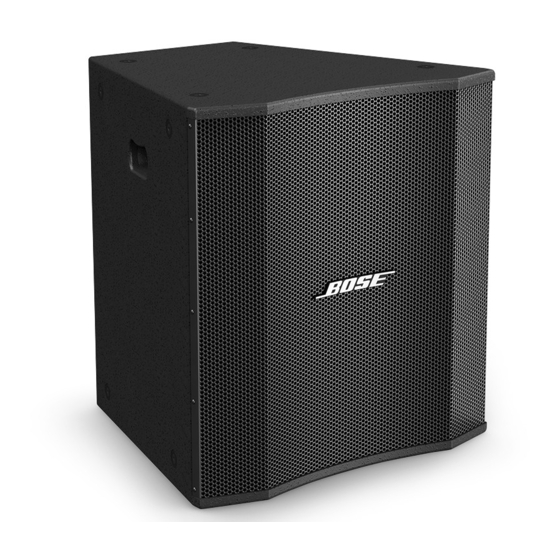
Bose LT 9403 Manual - Página 20
Navegue en línea o descargue pdf Manual para Altavoces Bose LT 9403. Bose LT 9403 35 páginas. Lt and mb series loudspeakers
También para Bose LT 9403: Manual de instalación (32 páginas), Manual de instalación (32 páginas), Manual del usuario (32 páginas)

8. 15 Inch Woofer Removal
Note: The LT 6400 and LT 9400 speakers do
not have a woofer.
8.1 Remove the 16 screws securing the
rear panel to the enclosure. Remove the
rear panel.
Re-assembly Note: When re-installing the
rear panel, be sure to torque the screws to
11 to 21 inch lbs.
8.2 Make a note of the wiring connections,
and disconnect the RED (+) and BLACK (-)
wires connected to the woofer.
8.3 Remove the 8 screws (11) securing the
woofer (10) to the enclosure.
8.4 Lift the woofer out of the enclosure.
Re-assembly Note: When re-installing the
woofer, be sure to torque the screws to 11
to 21 inch lbs.
Panaray
LT 6400 and LT 9400 Mid/High
®
Frequency Loudspeakers
CAUTION: The rear of the Panaray
and LT 9400 loudspeakers can become
extremely hot during normal use. Do not
attempt to service the loudspeakers until they
have cooled to room temperature.
Note: Refer to Figures 6 and 8 for the
following procedures.
1. Grille Removal
1.1 Remove the eighteen screws (21) that
secure the grille assembly (2) to the cabinet.
1.2 Lift the grille assembly off of the cabinet.
2. Logo Removal
2.1 Remove the grille using procedure 1
above.
Disassembly Procedures
LT 6400
®
20
2.2 On the back of the grille, carefully re-
move the slotted washer that retains the
spring and spacer against the back of the
grille. Note the direction the spacer faces.
Slide the spring and spacer off of the logo
post.
3. Input Panel Assembly Removal
3.1 Remove the six screws (11) that secure
the input panel assembly (10) to the cabinet.
Disconnect the cables that plug into the
PCB. Lift out the assembly.
3.2 Unplug the wiring harness at X1.
4. Crossover PCB Removal
4.1 Remove the eighteen screws (21) that
secure the grille assembly to the loud-
speaker. Lift off the grille.
4.2 Remove the twelve screws (18) that
secure the waveguide assembly to the
loudspeaker cabinet. Slowly slide out the
waveguide assembly and unplug the cable
wiring harness at X1.
4.3 Remove the screws (14) that secure the
crossover PCB assembly to the rear panel.
Lift off the crossover PCB assembly.
5. Audio Transformer Removal
5.1 Remove the eighteen screws (21) that
secure the grille assembly to the loud-
speaker. Lift off the grille.
5.2 Remove the twelve screws (18) that
secure the waveguide assembly to the
loudspeaker cabinet. Slowly slide out the
waveguide assembly and unplug the cable
wiring harness at X1.
5.3 Remove the two screws that secure the
audio transformer to the rear panel. Lift off
the audio transformer.
