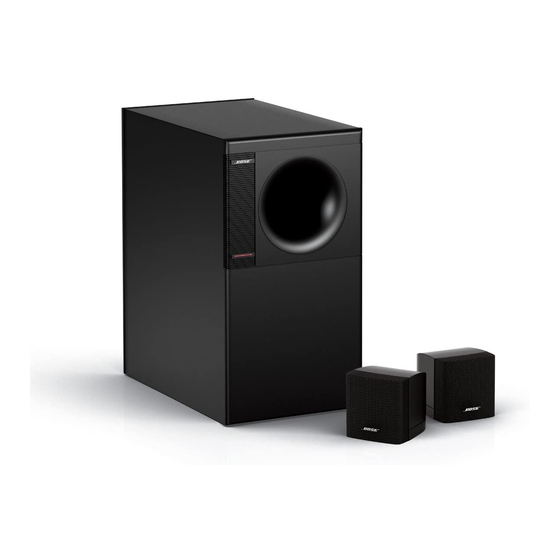
Bose Acoustimass 3 Series IV Manual del usuario - Página 8
Navegue en línea o descargue pdf Manual del usuario para Sistema de altavoces Bose Acoustimass 3 Series IV. Bose Acoustimass 3 Series IV 17 páginas. Bose acoustimass 3 series iv speaker system owner's guide
También para Bose Acoustimass 3 Series IV: Manual del usuario (22 páginas)

Setting Up Your Acoustimass
Connecting the cube speakers to the Acoustimass
Figure 3
Connecting the speaker cable
to the cube speaker
Connecting the Acoustimass module to your receiver or amplifier
6
®
3 Speaker System
Use the following steps to connect the cube speakers to the rear panel of the Acoustimass
module:
1. Select one pair of wires, and locate the terminal tab on the rear of the left cube speaker.
2. Press the terminal tab on the back of the speaker and insert the marked wire into the red
(+) terminal and the plain wire into the black (–) terminal (Figure 3).
3. Release the terminal tab to secure both wires.
4. Repeat this process with the other pair of wires and the right cube speaker.
CAUTION: Do not connect your amplifier or receiver directly to the cube speakers. Cube
speakers must be connected directly to the Acoustimass module or damage will result.
5. Locate the terminals marked OUTPUTS TO CUBE SPEAKERS on the rear panel of the
Acoustimass module (Figure 4).
6. Connect the free end of the left cube speaker cable to the left (L) pair of terminals. Make
sure that the marked wire is connected to the positive (+) terminal and the plain wire is
connected to the negative (–) terminal.
7. Repeat step 6 for the right cube speaker cable, connecting its wires to the right (R) pair of
terminals.
Use the following steps to connect your Acoustimass module to your receiver or amplifier:
CAUTION: Correct wiring is important. Incorrect wiring will result in little or no bass output
and could potentially damage the system.
1. Locate the terminals marked INPUTS FROM AMP OR RECEIVER on the rear panel of the
Acoustimass module (Figure 4).
2. Connect either end of one of the remaining speaker cables to the left (L) pair of input
terminals. Make sure that the marked wire is connected to the positive (+) terminal and the
plain wire is connected to the negative (–) terminal.
3. Connect either end of the final speaker cable to the right (R) pair of input terminals. Make
sure that the marked wire is connected to the positive (+) terminal and the plain wire is
connected to the negative (–) terminal.
October 22, 2001
module
®
AM252171_02_V.pdf
