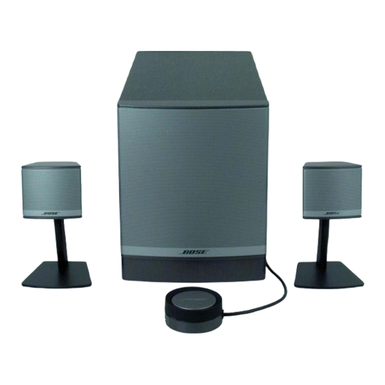
Bose Companion 3 Series II Manual del usuario - Página 8

Navegue en línea o descargue pdf Manual del usuario para Sistema estéreo Bose Companion 3 Series II. Bose Companion 3 Series II 19 páginas. Multimedia speaker system
También para Bose Companion 3 Series II: Manual del usuario (40 páginas), Manual del usuario (40 páginas), Manual del usuario (22 páginas), Manual del usuario (10 páginas), Manual del usuario (20 páginas), Manual del usuario (26 páginas), Manual de configuración rápida (2 páginas), Manual de configuración rápida (2 páginas), Instrucciones detalladas de montaje (2 páginas), Manual de instalación (20 páginas), Especificaciones (6 páginas), Folleto y especificaciones (4 páginas), Manual de servicio (36 páginas), Manual de servicio (16 páginas)

Bose Companion 3 Series II Manual del usuario
S
C
ETUP AND
ONNECTIONS
Figure 4
Removing a speaker from
the stand (a) and applying
rubber feet (b) to the
speaker

Making connections

8
Other suggestions:
• Use the supplied audio input cable, which allows for placement of the module up to 6 feet
(2 m) from your sound source.
• To place the module farther from the source, use a shielded audio input extension cable
available from retail electronics stores.

Positioning the speakers

The supplied speaker cables allow the speakers to be set up within 6 feet (2 m) of the
module.
The speakers are designed for desktop placement on stands that lift them slightly above the
surface or for resting directly on it.
If you prefer to use the speakers without stands, removing them is simple (Figure 4). After
removing a speaker from the stand, apply the supplied rubber feet to the bottom surface
for stability.
CAUTION: &KRRVH D VWDEOH OHYHO VXUIDFH IRU WKH VSHDNHUV DQG VWDQGV 9LEUDWLRQ FDQ FDXVH
WKHP WR PRYH SDUWLFXODUO\ RQ VPRRWK VXUIDFHV OLNH D GHVNWRS
Keep the speakers:
• Up to 3 feet (91 cm) from the sides of the screen.
• At equal distance on each side of the computer monitor or TV and slightly angled away
from it (Figure 2 on page 7).
a.
Custom cables supplied with this system simplify connections to the labeled jacks on the rear
®
of the Acoustimass
module (Figure 7).
CAUTION: 'R QRW SOXJ WKH $FRXVWLPDVV PRGXOH LQWR DQ $& SRZHU PDLQV RXWOHW XQWLO DOO WKH
VRXUFH FRPSRQHQWV DUH FRQQHFWHG WR WKH PRGXOH
B&RPSDQLRQB*XLGHIP
Français
Español
English
b.