Bose Companion 3 Series II Manual de servicio - Página 27

Navegue en línea o descargue pdf Manual de servicio para Sistema estéreo Bose Companion 3 Series II. Bose Companion 3 Series II 36 páginas. Multimedia speaker system
También para Bose Companion 3 Series II: Manual del usuario (40 páginas), Manual del usuario (40 páginas), Manual del usuario (22 páginas), Manual del usuario (10 páginas), Manual del usuario (20 páginas), Manual del usuario (26 páginas), Manual de configuración rápida (2 páginas), Manual de configuración rápida (2 páginas), Instrucciones detalladas de montaje (2 páginas), Manual de instalación (20 páginas), Especificaciones (6 páginas), Folleto y especificaciones (4 páginas), Manual del usuario (19 páginas), Manual de servicio (16 páginas)
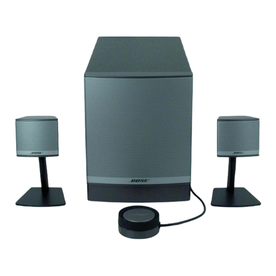
Bose Companion 3 Series II Manual de servicio
Theory of Operation
2.0
Main Amplifier Board (continued) (refer the schematic diagram 276762)
The signals coming into J308 (C7) are sent to sheet 3 of 3 (L_VOL and R_VOL). Three amplifiers in
U201 (D8-4) are the equalizers for the right channel and U125, (A8-4) are the equalizers for the left
channel. U951 (C8-3) in conjunction with U950 (C-2), the voltage controlled amplifier, form the bass
summer and dynamic bass equalizer.
The three stage equalizers for the equalizer perform the bass cutoff, mid-range cut, and high end
boost, in that order. They are 4-pole Salen-Key elliptical filters.
The bass signal is formed from the two inputs summed and low pass filtered by U951. The bass level
is detected by U125, D951, D952, Q950, Q951 and Q952 (B-6) forming an active peak detector. C955
and C957 filter the detected peaks to form the control voltage for the VCA in U950. When the bass
level is very low, the signal is boosted by U951. U950 is in the negative feedback path for U951, and
when its gain is low, U951 gain goes up, boosting the bass. U950 gain goes down when control
current generated by Q952 goes down, as controlled by peak detector circuit.
Q953, Q954 and D954 (D-2) form the peak detector on the bass outputs. Peaks near the negative rail
are conducted through D954 and Q953 to charge C969. Voltage on C969 is converted to a current by
Q954 which controls the VCA in U950. U950 is in the negative feedback loop of U951, so when U950
gain is high, less bass is output. Near clipping detected by the peak detector is converted to high
current by Q954, causing high gain in U950, reducing the gain in U951 and less bass. R980 and
C969 determine the attack time of the compressor, and R981 and C969 determine the release time.
Also on sheet 3 of 3, U201 (A-3) is the virtual ground generator. The 10 volt line is divided by two
R225 and R226, filtered by C970 and C235, and input to U201. The 5 volts generated by U201 is
used by all the signal processing circuitry as the virtual ground reference.
The right and left outputs, EQ_R and EQ_L are sent to page 2 of 3 (B3). U102 (B3) forms the true
space processing and the satellite signal compressors. TrueSpace™ processing consists of U102B
and U102D which act a low pass filters with a -3 dB point of 3 kHz. This signal is subtracted from the
opposite channel signal by U102A and U102C.
R204 and R105 determine how much TrueSpace signal is subtracted. The 127K compared to the 10K
value of the main signal inputs gives a TrueSpace signal of -18 dB relative to the main signal. To keep
the levels the same in mono conditions, the same amount of low pass filtered signal is added back to
the main channel of itself, through R106 and R206.
The satellite compressor consist of D401, D402, and Q401 (D7) which detect the right and left chan-
nel level, charging C401 when the R+, R-, L+ and L- signals get near the negative rail. The compres-
sor attack time is determined by R403, and the release time is determined by R404. When C401
charges negatively, Q402 and Q403 convert this to current which increases the gain of U401A and
U401B. U401 is in the negative feedback path of U102A and U102C, and higher gain reduces the
gain through the satellite channels. Therefore, high signal levels near clipping reduces the gain of the
satellite channels, compressing the signals.
The compressed signals are sent to the main amplifier on sheet 1 of 3 over signals Sat_Drv_L and
Sat_Drv_R. The bass signal from the bass compressor on sheet 3 of 3, BASS_DRV, is sent to two
stages of bass equalization at U3B and U3D (D7). These form the 40 - 50 Hz boost, and the 100 Hz
cut for the bass box equalization.
27