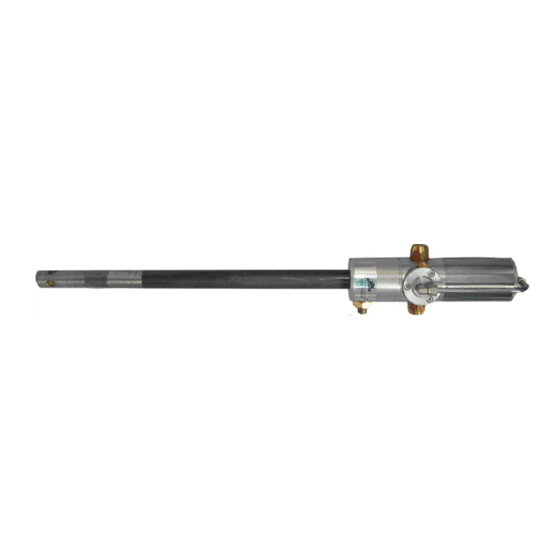
DROPSA 1524344 Series Manual de funcionamiento y mantenimiento - Página 5
Navegue en línea o descargue pdf Manual de funcionamiento y mantenimiento para Bomba de agua DROPSA 1524344 Series. DROPSA 1524344 Series 8 páginas. Pneumatic pumps for grease

- MAXIMUM PRESSURE 600 bar (8820 psi)
DRUM COVER IN PRESSED STEEL
- DIAMETER 330 mm (13 in.)
- INLET DIAMETER 28 mm (1.1 in.)
- COMPLETE WITH 3 FIXING STUDS
TO THE DRUM AND A PUMP FIXING STUD
PIPE FOR GREASE R2T – ¼" FF
LENGTH 1.5 M. FLEX.
-
OPERATING PRESSURE 350 - 400 bar (5145 - 5880 psi)
-
MAXIMUM PRESSURE 600 bar (8820 psi)
-
BURSTING PRESSURE 1200 bar (17640 psi)
-
6. UNPACKING AND INSTALLING THE PUMP
Before shipment, the pump is carefully packed inside a cardboard box. During transport and storage of the pump, pay
attention to the direction indicated on the box.
Upon receipt, check that the packaging is not damaged and store the pump in a dry place.
6.1 UNPACKING
Once the suitable location for installation has been identified, open the packing and remove the pump. Ensure that no
damage occurred during transport and storage.
The packing material does not require special disposal precautions as it is in no way dangerous or pollutant.
6.2 PUMP ASSEMBLY
Provide suitable space for the installation. Mount the pump at labourer height in order to prevent abnormal posture or
possible impact. Do not install the pump in particularly aggressive or explosive/flammable environments or on parts subject
to vibration.
1. position the grease drum on the carriage after fixing the base of the carriage to the column using the sliding housing
2. insert the grease pusher disc into the drum and close the drum using the cover, sliding it on the column after having
removed, if necessary, the handle
3. tighten the cover using the handles, centring the drum with respect to the cover
4. insert the pumping element of the pump into the centring holes on the cover and on the grease pusher disc
5. lock the pump into place on the cover using the specific handle
6. connect the grease output pipe in position
7. connect the air line and adjust the intake pressure using one of the following devices:
• PRESSURE REDUCER necessary where the compressed air system does not have one. Suitable for non-continuous use;
• PRESSURE REDUCER with CONDENSATION SEPARATOR, 50 micron filter, active carbon model, indispensable in all
types of pumps for continuous use, more than 10 minutes, prevents condensation from forming that can cause the
pump to lock up
• PRESSURE REDUCER with CONDENSATION SEPARATOR and LUBRICATOR, 50 micron filter, active carbon model,
suitable for fixed systems.
Note: The field of adjustments goes from a minimum of 4 bar (58.8 psi) to a maximum of 8 bar (117.6 psi)
7. OPERATING INSTRUCTIONS
5
