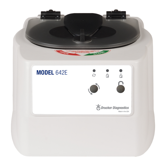
Drucker Diagnostics 642E Manual de servicio - Página 7
Navegue en línea o descargue pdf Manual de servicio para Equipos de laboratorio Drucker Diagnostics 642E. Drucker Diagnostics 642E 16 páginas.
También para Drucker Diagnostics 642E: Manual del usuario (8 páginas)

e) To install the lid tray, slide it onto the studs, and secure it with two #6 Nylok nuts, hand
tight.
f) Complete the installation by gently plugging the wire harness into the PCB header 'J4'.
The header and connector are keyed for proper orientation.
6.10 Replacing the PCB
a) The PCB is accessible once the cabinet has been removed. Make certain that all wire
harnesses have been disconnected.
b) The PCB has capacitors that will remain charged for a period after the centrifuge is
unplugged. Make certain to use standard precautions for handling potentially charged
capacitors when working with the PCB.
c) The PCB is held in place with four #6 Nylok nuts and plastic insulator washers. Use a
5/16" nut driver to remove the nuts. The PCB and washers are now free to slide off the
threaded studs.
d) Beneath the PCB are four plastic standoffs. If they are crushed, replace them before
reassembly.
e) To install the PCB, make certain that four plastic standoffs are present on the control
panel studs.
f) Slide the board onto the studs
g) Install four plastic washers onto the studs.
h) Important: over tightening the PCB nuts will cause malfunction – Each nut sets the
height of a separate control panel switch. Too low, and they cannot be actuated, too
high and they jam against the front panel label, and are always in the 'ON' state.
i) Tighten the nuts only until the buttons on the control panel click when pressed – do not
over tighten. Each nut sets the height of a separate control panel button. Tighten each
nut a ¼ turn in succession, trying each corresponding button as you go.
j) Once each control panel button clicks when pressed, installation is complete.
6.11 Removing the motor
a) Remove the cabinet assembly as previously described.
b) Cut and remove all wire harness zip ties.
c) Flip the base assembly up-side down and drill off the heads of the three exhaust air
channel rivets with a 3/16" drill bit.
d) Set the exhaust cover aside
e) The guard bowl is held in place with six low-profile head rivets, 5/32 nominal diameter.
To remove them, drill the heads off with a 3/16" drill bit.
f) Lift the base assembly off of the guard bowl and set it aside.
g) Flip the guard bowl.
DRUCKER DIAGNOSTICS
MODEL 642E SERVICE MANUAL
SM006
REV: A
7
