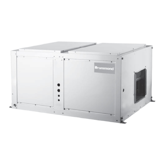
Drummond MOV-90CN1-D Manual de instalación - Página 9
Navegue en línea o descargue pdf Manual de instalación para Aire acondicionado Drummond MOV-90CN1-D. Drummond MOV-90CN1-D 16 páginas. Split system cooling only, r-410a refrigerant
También para Drummond MOV-90CN1-D: Manual del usuario (11 páginas)

b. Leakage detection alarm device linked
with the mechanical ventilation device
Indoor unit
OA
(The leakage detection alarm device should be installed at the place
vulnerable to retention of the refrigerant)
4.14 Completing The Connection System Name
In case multiple systems are set, in order to identify the connec-
tion system of the indoor unit and outdoor unit, it is necessary to
give name to each system, and mark it onto the nameplate on
the electric control box cover of the outdoor unit.
NOTE
NOTE
The indoor unit and outdoor unit are categorized into system A
and system B. When installing and connecting the indoor unit
and outdoor unit, identify the label carefully, and make sure that
indoor unit corresponds to the outdoor unit exactly. Otherwise, it
may lead to fault of the air conditioner.
Model of indoor unit. Room name
Example: The first system indoor unit (A) of the 2nd floor is
recorded as: 2F 1A
5. HEAT INSULATION OF THE PIPE
5.1 Heat Insulation Of The Pipe
In order to prevent faults caused by condensate of the refriger-
ant pipe and drain pipe, perform condensate prevention and
heat insulation properly.
CAUTION
If it is forecast that high humidity/temperature environment
(condensate temperature is over 23 ) may exist in the ceiling,
e.g., inside the ceiling with slab, ceiling which is in the same
environment as the outdoor air), it is necessary to apply 10mm
or thicker adiabatic wool (16~20kg/m
and the drain pipe in addition to applying the general heat insula-
tion materials. Enough heat insulation materials should also be
applied to the refrigerant joint and the pipe joint.
5.2 Heat Insulation Of The Drain Pipe
Be sure to entwine heat insulation materials round the drain pipe
which runs through the room.
Carry through heat insulation for the drain pipes thoroughly.
Installation Manual
8
5.3 Heat Insulation Of The Refrigerant Pipe
a. Ventilation orifice part
Fig.4-13
6. INSTALL THE CONNECTIVE PIPE
6.1 Preparation Before Installation
6.2 PRECAUTIONS DURING BRAZING OF LINES
2
) to the refrigerant pipe
Please use heat-resistant materials as heat insulation materials
of the air-side pipe. (e.g., EPT)
Cover heat insulation materials separately at the liquid side and
the air side. Moreover, perform heat insulation thoroughly for the
air-side pipes of the indoor unit, and prevent water from dripping
outside the unit.
(air-side pipe)
After applying the auxiliary heat insulation materials, use
vinylresin tape to seal it lest water leak.
Check the height difference between the indoor unit and the
outdoor unit, and check the length and number of bends of the
refrigerant pipeline, which must meet the following require-
ments:
Max. height difference....20m (If the height difference is greater
than 5m, it is best to put the outdoor unit above the indoor unit)
Max. pipeline length.........30m
Max. number of bends....15
In the process of installing the connective pipe, do not let the
air, dust or foreign substance intrude into the pipeline
system.
Install the connective pipe only after fixing the indoor and
outdoor units.
Keep dry when installing the connective pipe. Do not let moist
intrude into the pipeline system.
All outdoor unit and evaporator coil connections are copper-to-
copper and should be brazed with a phosphorous-copper alloy
material such as Silfos-5 or equivalent. DO NOT use soft solder.
The outdoor units have reusable service valves on both the
liquid
and
vapor connections. The
charge is retained within the outdoor unit during shipping and
installation. The reusable service valves are provided to evac-
uate and charge per this instruction
Serious service problems can be avoided by taking adequate
precautions to assure an internally clean and dry system.
CAUTION
Dry nitrogen should always be supplied through the tubing while it
is being brazed, because the temperature required is high enough
to cause oxidation of the copper unless an inert atmosphere is
provide. The flow of dry nitrogen should continue until the joint has
cooled. Always use a pressure regulator and safety valve to insure
that only low pressure dry nitrogen is introduced into the
tubing. Only a small flow is necessary to displace air and prevent
oxidation.
Indoor unit
Fig.5-1
total system
refrigerant
