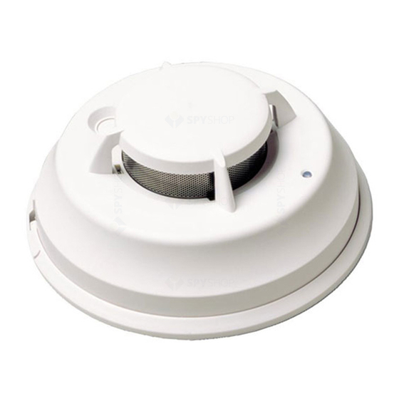
DSC FSB-210B Instrucciones de instalación y funcionamiento - Página 2
Navegue en línea o descargue pdf Instrucciones de instalación y funcionamiento para Alarma de humo DSC FSB-210B. DSC FSB-210B 4 páginas. Fsb-210 series smoke detector

Install Smoke detectors in accordance with NFPA 72,
Chapter 11:"Smoke detectors shall be installed outside
of each sleeping area in the immediate vicinity of the
bedrooms and on each additional story of the family liv-
ing unit, including basements and excluding crawl spaces
and unfinished attics. In new construction, a smoke
detector also shall be installed in each sleeping room."
2. Mount Smoke Detector
Backplate
Mount backplate on standard
4" octagonal electrical box
using the screws provided.
NOTE: Power supply must be
supplied from a UL Listed
alarm control unit. Install wir-
ing in accordance with the
appropriate national and local
electrical codes.
3. Wiring
ing power to the unit. When the wiring has been
thoroughly reviewed, neatly insert the wires into the elec-
trical box and secure the unit to the mounting plate.
NOTE: This equipment should be installed in accordance
with the National Fire Protection Association Standard 72
(National Fire Protection Association, Batterymarch Park,
Quincy, MA 02269).
Dust Cover
The dust cover is intended to protect the smoke detector
from dust and dirt entry while the unit is not in service.
CAUTION: The dust cover protects the unit ONLY when it
is not in service. Remove the dust cover before use.
Device Enrollment
The serial number located on the back of the device must
be enrolled into the alarm control panel via Installer's Pro-
gramming ([ ][8] [Installer Code]). This procedure is out-
lined for Power panels in the PC5100 Installation Manual
and for the PC4010/4020 v3.x in the control panel Instal-
lation Manual.
WARNING: Connect only DSC addressable series
devices to the addressable loop connections. Connec-
tion of any other type of device will impair operation.
Devices other than addressable series devices which
require power to operate must be powered separately.
Locking
Tab
Mounting Holes
Refer to the connection dia-
gram in this section. Before
connecting the unit, prepare
the wires from the electrical
box for connection; the wires
should not be frayed or bent.
CAUTION: If power connec-
tions are reversed, the unit
will not operate. The unit is
protected against damage
from incorrect wiring.
When wiring is completed,
inspect the wiring and cor-
rect any errors before apply-
Do NOT use looped wire under terminals for system
supervision. Break the wire run to provide supervision
of connections.
4. Mounting
Detector Installation
Position the detector on to the base plate using the
detector and base plate alignment marks. Press the
detector gently in place while rotating the detector clock-
wise until the detector snaps into place. Remove the side
tab from the locking tab to lock in place (optional).
Removal: If the side tab
is removed to lock the
detector,
depress
tab
with a small flat blade
screwdriver and rotate
the detector counter-
clockwise
until
the
alignment
marks
line
up. Remove detector.
5. Test Unit
1. Program the Panel for Smoke Test. Refer to the Alarm
Control Panel Installation Manual for details.
NOTE: If the detector is in one of the following states
when test is initiated, it will not enter an alarm state:
• Compensation trouble.
• Failure of heat or smoke detector.
• Other internal faults that could prevent a smoke or
heat alarm.
2. Use the FSD-100 meter to read the trouble status after
testing. Refer to the FSD-100 User Guide for details.
NOTE: Place the meter close to the LED until it begins to
flash every 2 seconds. Then hold the meter on the oppo-
site side of the LED and read the message. The detector
will send out a test message 7 times in a 2-second inter-
val until the LED stops flashing.
6. Compensation Reset
Cleaning, replacement of the smoke sensor, or other
changes may change the background signal/noise of the
detector; this requires the drift compensation be reset.
Compensation trouble is one of the faults indicated when
the LED indicator is OFF.
• Remove power from the unit, then press and hold the
test button for 30 seconds to power down unit.
• Power up unit while pressing the test button.The LED
will flash; when 5 seconds has elapsed. Release the
test button within 1 second after the fifth LED flash.
• The LED will flash every 8 seconds for 1 minute.
When the detector stops flashing test the detector to
verify normal operation.
Mounting
Surface
Backplate
Alignment
Tabs
Marks
Detector
CLOSE
OPEN
