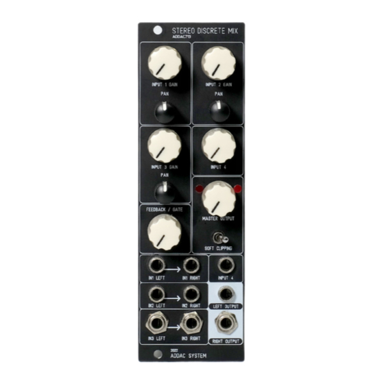
ADDAC System ADDAC713 Manual de montaje - Página 12
Navegue en línea o descargue pdf Manual de montaje para Mezclador de música ADDAC System ADDAC713. ADDAC System ADDAC713 13 páginas. Stereo discrete mixer
También para ADDAC System ADDAC713: Manual del usuario (5 páginas)

ADDAC713 Assembly Guide
Calibration
TUNING THE BIAS:
An oscilloscope is required to precisely adjust the bias.
1. Start by turning all Inputs and the Feedback/Gate knobs fully
counter-clockwise and set the MASTER OUTPUT at 12 o'clock.
2. Plug a Triangle waveform into INPUT 1 LEFT and connect the
LEFT OUTPUT to the oscilloscope.
3. Raise the INPUT 1 GAIN knob until you can see clipping occur on
the oscilloscope, notice the clipping will appear at one of the rails
first, meaning the audio bias is not centered at 0v, rotating the Left
Channel Trimmer will adjust the bias until a "balance" is achieved,
the clipping should occur at both at the top and bottom rail where
the positive waveform mirrors the negative waveform.
4. Repeat the procedure for the Right Channel.
These trimmers can also be used to change the timbre of the
distortion effect as non-mirrored clipping will have a strong impact
on the new harmonics generated.
Mods
INPUTS GAIN MODIFICATIONS:
By default we calibrated the inputs to have a large range of
amplification. This default value is what we thought of as a good
compromise however other values were possible.
We decided to leave it up for the user if further adjustment is
prefered.
Experience soldering smd 0603 resistors required, we take no
responsability if the user permanently damages the pcb in this
process!
The default value for all resistors is 1K
Lower values resistors (up to 100R) will increase the maximum gain.
At higher volume levels this will add more grit and higher harmon-
ics, at lower volume levels you'll notice an increase in background
noise as well as channel bleeding.
Higher values will reduce the maximum gain, by reducing the max
gain the gain knobs will travel longer until the signal starts clipping
mallowing for better control of clean signals.
Resistor positions shown here.
ADDAC SYSTEM
TRIMMER LOCATIONS
RIGHT
CHANNEL
BIAS
LEFT
CHANNEL
BIAS
CH1R>
CH3L>
CH3R>
CH1L>
<CH2R
page 12
