dtec DYNertia3 Manual de inicio rápido - Página 4
Navegue en línea o descargue pdf Manual de inicio rápido para Instrumentos de medida dtec DYNertia3. dtec DYNertia3 20 páginas.
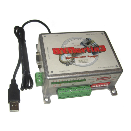
DYNertia3 Quick Start (Inertia- Chassis type)
Concept
An inertia type dyno operates on the principle of calculating the power required to accelerate a known mass, which is
basically just an additional 'roller/flywheel' driven by the vehicle. The controller senses the velocity of this rotating mass,
handles the precision timing required and outputs this data to the PC for analysis and storage.
The included 'DYNertia3' software package handles all the functions required for dyno control, setting up, saving runs,
correcting for atmospheric conditions, filtering, displaying data, printing, overlaying and analyzing multiple runs.
Hardware Mounting & Basic Wiring for Initial Setup
Mounting the DYNertia Sensor and Magnet
Mount the sensor system to detect the rotation of the roller/shaft.
Note:
Do not mount the magnet at the outside diameter of the dyno roller/shaft as the centrifugal forces will be highest;
choose a location towards the centre area. The magnet is also very fragile and must be handled with care!
The included sensor will only detect the 'South' Pole of a magnet, so the magnet must be have the South Pole
Note:
(marked with red paint) facing the sensor!!
Magnet epoxy glued and screwed to dyno flywheel with South Pole outwards.
Mounting by screwing/gluing flat to dyno flywheel-
Dyno flywheel is drilled and tapped for 3mm screw (2.5mm drill size is
usual for 3mm tapping). Short (min 6mm) screw inserted into magnet.
Do not over tighten or magnet may crack!
The sensor face
magnets
South Pole
to secure magnet).
www.dtec.net.au
must be positioned 1.5 - 2mm
(or the head of the screw if one is used
from the
4