Comtrol RocketLinx ES8105F-M Manual del usuario - Página 9
Navegue en línea o descargue pdf Manual del usuario para Interruptor Comtrol RocketLinx ES8105F-M. Comtrol RocketLinx ES8105F-M 16 páginas.
The Ethernet cables use Pins 1, 2, 3, and 6 of an 8-pin RJ45 connector. The signals of these pins are converted by the automatic
MDIX function, as shown in the following table.
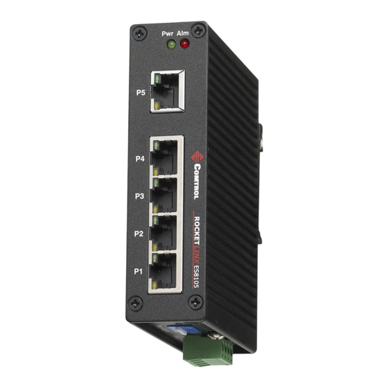
Connect one side of an Ethernet cable into any switch port and connect the other side to your attached device. The LINK/ACT
LED is lit when the cable is correctly connected. Always make sure that the cables between the switches and attached devices
(for example, switch, hub, or workstation) are less than 100 meters (328 feet).
The wiring cable types and maximum cable length are as follows.
•
10BASE-T: 2-pair UTP/STP Category 3, 4, 5 cable, EIA/TIA-568 100-ohm (100 meters)
•
100BASE-TX: 2-pair UTP/STP Category 5 cable, EIA/TIA-568 100-ohm (100 meters)
Connecting the Fiber Port (RocketLinx ES8105F)
Connect the fiber port on the RocketLinx ES8105F to another fiber Ethernet device using the following information.
A wrong connection will cause the fiber port not to work properly.
Connecting the Fiber Port (RocketLinx ES8105F)
Pin
MDIX Signals
1
RD+
2
RD-
3
TD+
6
TD-
This is a Class 1 Laser/LED product.
Do not stare into the Laser/LED beam.
Caution
MDI Signals
TD+
TD-
RD+
RD-
RocketLinx ES8105/ES8105F User Guide: 2000558 Rev. B - 9
Hardware Installation