3onedata IES7120-4GS-2F Manual del usuario - Página 3
Navegue en línea o descargue pdf Manual del usuario para Interruptor 3onedata IES7120-4GS-2F. 3onedata IES7120-4GS-2F 5 páginas. Industrial
【Console port】
This series product provided 1pcs procedure test port based in
serial port. It adopts RJ45 interface, located in top panel, can
configure related command through RJ45 to DB9 female cable.
【Communication connector】
10/100BaseT(X) Ethernet port
The pinout define of RJ45 port display as below, connect by UTP
or STP. The connect distance is no more than 100m. 100Mbps is
used 120Ω of UTP 5, 10Mbps is used 120Ω of UTP 3, 4, 5.
RJ 45 port support automatic MDI/MDI-X operation. can
connect the PC, Server, Converter and HUB .Pin 1,2,3,6
Corresponding connection in MDI. 1→3, 2→6, 3→1, 6→2 are
used as cross wiring in the MDI-X port of Converter and HUB.
10Base-T/100Base-TX are used in MDI/MDI-X, the define of Pin
in the table as below.
NO.
MDI signal
1
TX+
2
TX-
1
8
3
RX+
6
RX-
—
4, 5, 7, 8
Note: "TX±"Transmit Data±, "RX±"Receive Data±, "—" Not use.
10/100Base-T(X) MDI (straight-through cable)
10/100Base-T(X) MDI-X (Cross over cable)
MDI/MDI-X auto connection makes switch easy to use for
customers without considering the type of network cable.
100Base-FX Fiber port
100Base-FX full-duplex SM or MM port, SC/ST/FC type .The
fiber port must be used in pair, TX (transmit) port connect remote
switch's RX(receive) port; RX(receive) port connect remote
switch's TX(transmit) port.
The optical fiber connection supports the line to instruct
enhance the reliability of network effectively.
Suppose: If you make your own cable, we suggest labeling
the two sides of the same line with the same letter (A-to-A and
B-to-B, shown as below, or A1-to-A2 and B1-to-B2).
MDI-X signal
RX+
RX-
TX+
TX-
—
- 3 -
1000Base SFP fiber port(mini-GBIC)
1000Base-FX SFP fiber port adopts gigabit mini-GBIC
transmission, can choice different SFP module according to
different transfer distance. Fiber interface must use for pair, TX
port is transmit side, must connect to RX (receive side). The fiber
interface support loss line indicator.
Suppose: If you make your own cable, we suggest labeling the
two sides of the same line with the same letter (A-to-A and
B-to-B, shown as below, or A1-to-A2 and B1-to-B2).
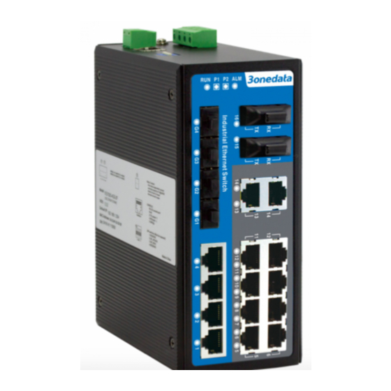
【LED Indicator】
LED indictor light on the front panel of product, the function of
each LED is described in the table as below.
System indication LED
LED
State
Description
Power is being supplied to power
ON
input PWR1
P1
Power is not being supplied to
OFF
power input PWR1
Power is being supplied to power
ON
input PWR2
P2
Power is not being supplied to
OFF
power input PWR2