Auber Instruments JSL-64A Manual de instrucciones - Página 4
Navegue en línea o descargue pdf Manual de instrucciones para Timer Auber Instruments JSL-64A. Auber Instruments JSL-64A 5 páginas. 1/32 din general purpose timer

AUBER INSTRUMENTS
Note 8. The parameter STOP defines the relay output status when STP key is
pressed during timer T1 is counting.
(** The parameter STOP parameter will only appear in the menu when FUNC =
SDL and OUT = ONDL.)
When running the single-delay (FUNC = SDL) and on-delay mode (OUT =
ONDL), depending on the applications, user may want the output relay
(normally open) to stay at off position (which is the initial status), or, stay at on
position (which is the relay's final status) when the STP key is pressed. Here
are two examples. A) Some users use the timer to turn on a buzzer at the end
of a process for notification purpose. They want to be able to disable the
buzzer (change to the initial status) by simply pressing down the stop button
once he acknowledged the notification. B) Some users want to delay the
process of turning on a load. But sometimes, they may want to cancel the
delay (change to the final state) to start the oven by pushing the stop key.
In order to satisfy these two conflict requirements, a special parameter for stop
function, STOP will show up in the parameter menu when both ONDL (on
delay) and SDL (single delay) are selected, STOP can be selected as 0
(default) or 1. When it is set to 0, during the delay, stop signal will set relay to
the final state (pulled-in). When it is set to 1, during the delay, stop signal will
set the relay to the initial state (dropped-out). When the time delay is finished
and relay pulled in, user can reset the relay to the initial state by sending a stop
signal, regardless of the STOP setting.
Note 9. The parameter PAUS defines whether the relay output (pin 4 and 5)
should be changed from ON to OFF while the timer is running and the PAU key
is pressed. When PAUS = 0, pressing the PAU key will only pause the timer
and it will NOT affect the relay output status. When PAUS = 1, pressing the
PAU key will not only pause the timer but also change a relay output status
from ON to OFF. However, it will not affect relay status if the relay is OFF.
7. Wiring Examples
1) Signal controlled by switches
Power (120 or 240V AC) is sent to pin 1 and 2. The external reset (RST) and
pause (PAU) switch should be momentary type. They are needed only if you
want to control the timer remotely. Otherwise, you can use the front keys on
the timer. These switches can also be replaced with a control signal from
computer or other control devices. The alarm speaker used in this example
is also optional. It is to show how to wire the output. You can substitute it
with any output such as a coffee grinder. The output terminals (#4 and 5)
are from an internal relay. It is a dry switch that does not provide the power by
itself. In this case, the alarm is powered by the 120VAC. The external switch
connected to the alarm is for disabling the sound if needed.
2021.03
PAU
RST
Figure 5. Connecting reset switch and pause switche to JSL-64A.
2) Signal controlled by DC logic signal.
Figure 6. Rising-edge triggered signal.
Figure 7. Inverted logic signal.
3) Espresso shot timer
In this example, we will use a small relay (120V coil voltage and a pair of
normally open NO contacts) with JSL-64A timer. The espresso machine use
120VAC power and it has a vibration pump that runs at 120VAC. To use this
timer as an espresso shot timer, please set FUNC = EST, and T1U = S. Then
press RST key to clear the screen. The display will show "0.00" as shown in
the Figure 8 below. Wiring of the timer, relay, and the pump is shown in the
Figure 9 below.
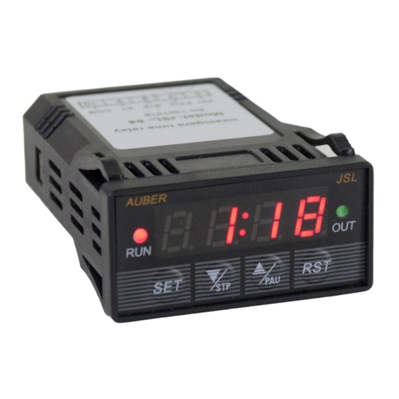
Figure 8. The display of the JSL-64A timer in ESP mode.
WWW.AUBERINS.COM
L
120VAC
N
P4/5
