3onedata TNS5500D Series Manual de instalación rápida - Página 2
Navegue en línea o descargue pdf Manual de instalación rápida para Interruptor 3onedata TNS5500D Series. 3onedata TNS5500D Series 4 páginas. 12-port series layer 2 wall mounting industrial ethernet switch
También para 3onedata TNS5500D Series: Manual de instalación rápida (4 páginas), Manual de instalación rápida (3 páginas), Manual de inicio rápido (5 páginas)

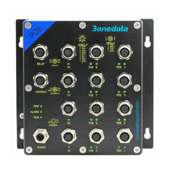
Right view
1.
Hanger
2.
Relay alarm output terminal block
3.
Console port
4.
Indicator of power supply input status PWR
5.
Relay alarm indicator ALARM
6.
Indicator of device running status RUN
7.
Grounding screw
8.
Power input terminal block
9.
10/100/1000Base-T(X) Gigabit copper port
10.
Gigabit copper port connection indicator
11.
100M copper port connection indicator
12.
10/100Base-T(X) 100M POE copper port
13.
POE indicator
14.
10/100Base-T(X) 100M copper port
【Mounting Dimension】
Unit: mm
Attention before mounting:
Don't place or install the device in area near water or
moist, keep the relative humidity of the device
surrounding between 5%~95% without condensation.
Before power on, first confirm the supported power
supply specification to avoid over-voltage damaging the
device.
The device surface temperature is high after running;
please don't directly contact to avoid scalding.
【Wall-mounting the Device】
Step 1
Put the device on the wall it will be mounted as
reference or to refer to its mounting dimension, and
mark the locations of the 4 expansion screws.
Step 2
Mount the screws on the wall and reserve 7mm
void.
Step 3
Hang the device on the 4 expansion screws and
slide it down, then tighten the screws, mounting
ends.
【Disassembling the Device】
Step 1
Device powers off
Step 2
Unscrew the screws on the wall about 7mm.
Step 3
Lift the device then take it out, disassembling ends.
Note:
Power ON operation: first connect power line to the
connection terminal of device power supply, then power
on.
Power OFF operation: first unpin the power plug, then
remove the power line, please note the operation order
above.
【Power Supply Connection】
DC power supply
The series devices provide 1 power supply
input. The interface adopts M12 A-Coded 4-pin
needle (male) connector, which could be
connected to M12 A-Coded 4-pin slot (female).
Power supply range: 110VDC (70-160VDC).
The pin definitions of M12 (Male) are as follows:
No.
1
2
Definition
FG
V-
Description
Ground
Power
input
negative
3
4
V+
NC
Power
reserved
input
positive
