3onedata TNS5800-8GP16GT-P24VDC Manual de instalación rápida - Página 2
Navegue en línea o descargue pdf Manual de instalación rápida para Interruptor 3onedata TNS5800-8GP16GT-P24VDC. 3onedata TNS5800-8GP16GT-P24VDC 3 páginas. Rack-mounted industrial ethernet switch
The device surface temperature is high after running;
please don't directly contact to avoid scalding.
【Rack-mounted】
Step 1
Select the device mounting location to ensure
enough size.
Step 2
Put the device on the plane plate of the rack, and
install the left and right lugs on the rack with 4
screws.
Step 3
Check and confirm the product is mounted firmly on
the rack, mounting ends.
【Disassembling Device】
Step 1
Power off the device.
Step 2
Unscrew the fixed mounting lug screw on the rack.
Step 3
Shift out the device from rack, disassembling ends.
Notice before power on:
Power ON operation: First insert the power supply
terminal block into the device power supply interface,
then plug the power supply plug contact and power on.
Power OFF operation: First, remove the power plug,
then remove the wiring section of terminal block. Please
pay attention to the above operation sequence.
【Power Supply Connection】
The device provides 3-pin 5.08mm pitch
DC power terminal block, power supply
range: 24VDC (12-36VDC).
【Relay Connection】
This device provides 3-pin 5.08mm pitch
relay terminal blocks, which are a set of
normally open contacts of the device alarm relay. They are
open circuit in the state of normal non alarm, closed when any
alarm information occurs. For example, they are closed when
powered off, and send out alarm. The series of switch support
1 relay alarm information output that can output DC power
supply alarm information or network abnormality alarm. It can
be connected to alarm light or alarm buzzer or other switching
value collecting devices, which can timely inform operators
when the alarm occurs.
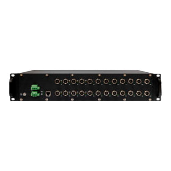
【Communication Interface Connection】
This device provides 24 10/100/1000Base-T(X)
interfaces, the interface type is M12 X-Coded
8-Pin slot (female), therein G1-G8 supports
PoE
function,
support
self-adaption. The pin definitions of M12 are shown as follows:
Pin No.
Pin Definition
Description
1
BI_(DA+)
Positive bi-directional data
of Gigabit Ethernet group 1
2
BI_(DA-)
Negative bi-directional data
of Gigabit Ethernet group 1
3
BI_(DB+)
Positive bi-directional data
of Gigabit Ethernet group 2
4
BI_(DB-)
Negative bi-directional data
of Gigabit Ethernet group 2
5
BI_(DD+)
Positive bi-directional data
of Gigabit Ethernet group 4
6
BI_(DD-)
Negative bi-directional data
of Gigabit Ethernet group 4
7
BI_(DC-)
Negative bi-directional data
of Gigabit Ethernet group 3
8
BI_(DC+)
Positive bi-directional data
of Gigabit Ethernet group 3
【Console Port Connection】
The device provides 1 program debugging port based on
RS232 serial port which can conduct device CLI command
management after connecting to PC. The interface adopts
RJ45 port, the RJ45 pin definition as follows:
Pin No.
Pin Definition
【Checking LED Indicator】
The device provides LED indicators to monitor its operating
status, which has simplified the overall troubleshooting
process. The function of each LED is described in the table
below:
LED
Indicate
ON
PWR
OFF
IEEE802.3at/af
ON
ALM
OFF
ON
RUN
OFF
Blinking
ON
Link/Act
Blinking
OFF
PoE
ON
OFF
【Logging in to WEB Interface】
This device supports WEB management and configuration.
Computer can access the device via Ethernet interface. The
way of logging in to device's configuration interface via IE
browser is shown as below:
Step 1
Configure the IP addresses of computer and the
2
3
5
TXD
RXD
GND
Description
Power is connected and running
normally
Power supply is disconnected or
running abnormally
Port link has alarm
Port link has no alarm
The
device
self-check
hasn't
finished or the device is abnormal.
The device is powered off or the
device is abnormal.
Blinking about 1 time per second,
system is running normally
Ethernet port has established a
valid network connection
Ethernet port
is in an active
network status
Ethernet port has not established
valid network connection
POE
port
is
powering
other
devices normally
POE is disabled or disconnected