3onedata IES618-4D(RS-232)-P Manual del usuario - Página 3
Navegue en línea o descargue pdf Manual del usuario para Enrutador de red 3onedata IES618-4D(RS-232)-P. 3onedata IES618-4D(RS-232)-P 6 páginas. Ies618-4d series industrial ethernet switch
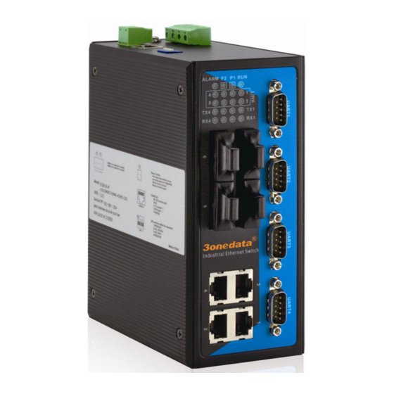
IES618-4F-4D(RS-232)-P(12/48VDC)
1. PWR1/PWR2 power supply
2. Ground screw
3. Relay output terminal block
4 Console port
5. DIP switch (4 bits)
6. DIN-Rail
7. RS-485/422 port
8. 10/100Base-TX RJ45 port
9. 100Base-FX fiber port
10. LED indicator
【Appearance and dimension】
Unit(mm)
Front view
【Power supply input】
Vertical view
IES618-4D series provide 4 bits industry terminal block (V1-,
V1+, V2-, V2+)), V-, V+ is 12~48VDC power supply input.
IES618-4D series DC power supply input supported
redundancy function, provided PWR1 and PWR2 power input,
can use for single, and can connect 2 separately power supply
system, use 1 pair terminal block connect the device at the same
time. If one of the power system broke, the device can work
un-interruptible. built-in over current protection, Reverse
connection protection
【Console port】
IES618-4D series provided 1pcs procedure test port based in
serial port. It adopts RJ45 interface, located in top panel, can
configure the CLI command through RJ45 to DB9 female cable.
Front view
【Relay connection】
The relay owns two contacts of the terminal block on the top
panel of IES618-4D series. It is used to detect both power failure
and port failure. The two wires attached to contacts form an open
Back view
circuit when:
(1) IES618-4D series has lost power supply from one of the
(2)
【DIP switch】
Top view
Vertical view
Top view
DC power inputs.
One of the ports is failure.
Top panel provided 4 bits DIP switch to do function
configure(OFF is default factory),1 and 4 keep for future
function. 3 is recovery default factory. 2 is for upgrade. Please
power off and power on when you change the status of DIP
switch.
【Communication connector】
10/100BaseT(X) Ethernet port
The pinout of RJ45 port display as below, connect by UTP or STP.
The connect distance is no more than 100m. 100Mbps is used 120
Ωof UTP 5 , 10Mbps is used 120Ωof UTP 3,4,5.
RJ 45 port support automatic MDI/MDI-X operation. can
connect the PC, Server, Converter and HUB .Pin 1,2,3,6
Corresponding connection in MDI. 1→3,2→6,3→1,6→2 are used
as cross wiring in the MDI-X port of Converter and HUB.
10Base-T/100Base-TX are used in MDI/MDI-X, the define of Pin
in the table as below.
NO.
MDI signal
1
TX+
1
8
2
TX-
3
RX+
6
RX-
—
4, 5, 7, 8
Note: "TX±"Transmit Data±, "RX±"Receive Data±, "—"Not Use。
MDI (straight-through cable)
MDI-X signal
RX+
RX-
TX+
TX-
—