Concoa 830-9413 Manual de instrucciones de instalación y funcionamiento - Página 3
Navegue en línea o descargue pdf Manual de instrucciones de instalación y funcionamiento para Unidad de control Concoa 830-9413. Concoa 830-9413 8 páginas. Relief valves
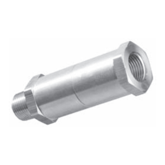
Table 1
Part
Material
Number
830-9414 Brass
830-9413 Brass
830-9412 Brass
FIELD ADJUSTMENT
Note: The safety relief device should not be used as a control valve to regulate
the system operating pressure. Frequent activation will cause seat leak and
require excessive maintenance.
DO NOT ADJUST WHILE UNDER PRESSURE.
1. Maintain system-operating pressure at least 5-10% below the set pressure
of the relief valve. Operating too close to the valve set pressure will cause
seat leak and will shorten the time between valve maintenance.
2. To adjust the cracking pressure, a field test bench maybe constructed
using the following parts as shown in Figure 2 below:
a. 492-1312-01-580
601-3312-01-580
b. 529-0022-01-001
c. 533-9002
d. 830-5385
Seat
Pressure
Range
Neoprene
80-120 PSIG
Viton
270-600 PSIG 12,864 SCFH (N2 420 PSIG)
Viton
130-310 PSIG
0-750 PSIG regulator
0-150 PSIG regulator
Reducing adapter
Needle valve
Brass ¼" tee
a
c
d
b
9400
Series
Relief
Valve
Figure 1
Flow at 10% Pressure
Differential
1,263 SCFH (N2 100 PSIG)
6,960 SCFH (N2 220 PSIG)
Figure 2