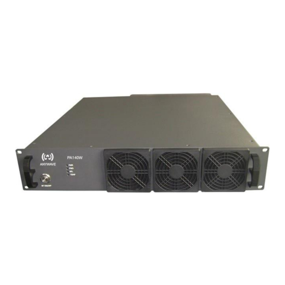
Anywave PA-140W Manual del usuario - Página 9
Navegue en línea o descargue pdf Manual del usuario para Transmisor Anywave PA-140W. Anywave PA-140W 13 páginas.

3 Control Interface
3.1 Local Control Interface
Local control and monitoring of the PA unit is accomplished via the ACT-5X Exciter front panel user
interface. Use a standard serial cable to connect the PA D9 RS232-A port to the ACT-5X Exciter D9
REMOTE (RS232) port. With this connection established, all the PA information will be displayed in the
PAC sub-menu in the advanced menu of ACT-5X exciter, as shown below:
VOL_9
VOL_50
Value
8.76V
50.35
Voltage of
Voltage of
Content
9V DC
50V DC
supply
supply
Note: The displayed settings and numbers in the tables below are for illustration purposes only and may be
different from those in actual use.
A second sub-menu is available for configuring the PA networking settings. Enter the main menu of
ACT-5X exciter and locate the PA_CNFG sub-menu to setup the IP, GATEWAY and MASK PA
networking parameters.
Default
192.168.001.210
Options
***.***.***.***
3.2 Serial Port Interface
The port RS232-B of PA is reserved to be used as serial port interface for remote control.
ACT-140PA-USR-DOC-V1.4, 09/12/2014
Table 1 PAC sub-menu in Advanced Menu
CUR_50
PA_FWD
12.04A
171.92W
Current of
Forward
50V DC
power of PA
power of PA
supply
Table 2 PA_CNFG sub-menu in Control Mode
IP
PA_REF
GV
VSWR
0.77W
1.69V
1.14
Grid
Voltage
Reflected
Voltage
standing
(bias
wave ratio
voltage)
GATEWAY
192.168.001.001
***.***.***.***
PA-140W User Manual
PA_TEMP
PA__LVL
CUR1_50
117.3℉
140W
9.8A
Temperature
PA rated
Device
of PA
power
Current
MASK
255.255.255.000
***.***.***.***
Page 9 of 13
