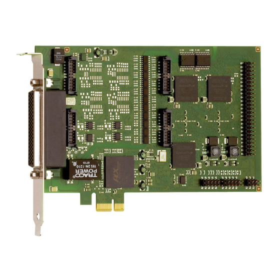
Addi-Data APCI-1710 Manual - Página 4
Navegue en línea o descargue pdf Manual para Hardware informático Addi-Data APCI-1710. Addi-Data APCI-1710 13 páginas. Multifunction counter board, optically isolated
También para Addi-Data APCI-1710: Descripción de la función (17 páginas), Descripción de la función (15 páginas)

Contents
Contents
Warning! ...........................................................................................................................................3
Chapter overview.............................................................................................................................5
1
Function description .............................................................................................................6
1.1
Board versions with "Pulse counter" function ...................................................................................6
1.2
Block diagram .......................................................................................................................................7
1.3
Used signals ...........................................................................................................................................7
1.4
Pin assignment: Function modules ......................................................................................................8
1.5
Connecting the pulse encoders............................................................................................................8
1.5.1
Connection to the screw terminal panel.............................................................................................8
1.5.2
Connection example ...........................................................................................................................10
1.6
Procedure for using the "Pulse counter" function...........................................................................10
2
Standard software ..............................................................................................................11
3
Appendix .............................................................................................................................12
3.1
Index ....................................................................................................................................................12
4
Contact and support ...........................................................................................................13
Figures
Block diagram: "Pulse counter" function .....................................................................................7
Pin assignment: 50-pin D-Sub male connector (4 pulse counter modules).................................8
Connection example.....................................................................................................................10
Tables
Table 1-1: Used signals .....................................................................................................................................7
Table 1-2: Connection of the pulse encoders to the screw terminal panel .................................................9
www.addi-data.com
4
PCI-1710: Pulse counter
