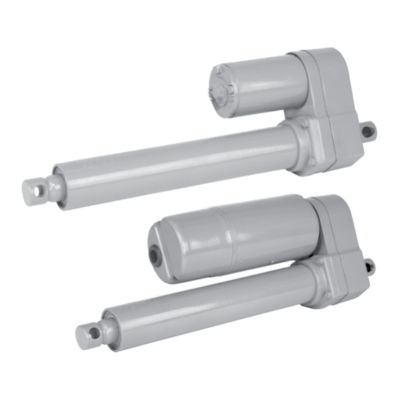
Duff-Norton TAP05-1A10 Series Instrucciones de instalación, funcionamiento y mantenimiento - Página 8
Navegue en línea o descargue pdf Instrucciones de instalación, funcionamiento y mantenimiento para Controlador Duff-Norton TAP05-1A10 Series. Duff-Norton TAP05-1A10 Series 12 páginas.

Index
Number
1
Gear housing
2
Shaft, cluster gear
3
Pinion
4
Screw, 10-32 x 3/4
5
Housing plate
6
O-ring, -142
7
Motor, 115 VAC
7a
Motor, 220-230 VAC
7b
Motor, 12 VDC
7c
Motor, 24 VDC
8
Lifting nut
9
O-ring
10
Spiral ring
11
Outer tube, 4" stroke
Outer tube, 8" stroke
Outer tube, 12" stroke
12
Flange, tube
13
Translating tube, 4" stroke
Translating tube, 8" stroke
Translating tube, 12" stroke
14
Rod seal
15
Clevis nut
16
O-ring, -022
17
Top clevis
18
Flanged bushing
19
Cluster gear, 20:1
Cluster gear, 10:1
20
Output gear, limit switch models
Clutch, 500 pound models
21
Gasket, housing
22
Nut, 1/2-20
23
Woodruff key, #304
24
Bearing, 6302Z
25
Screw, 4" stroke
Screw, 8" stroke
Screw, 12" stroke
26
Stop washer
27
Screw, 3/8-24 x 3/4
28
Screw, 12-24 x 2
Section V
Illustrated Parts List
Table 5-1. Linear Actuator Parts List
Part Name
Qty.
Req.
1
1
1
3
1
1
1
1
1
1
1
1
1
1
1
1
1
1
1
1
1
1
1
1
1
1
1
1
1
1
1
1
1
1
1
1
1
1
4
8
Part Number
EM1050-2
SK3410-43
SK3410-7
H2695PC
EM1050-1
X6477-137
EM1050-24
EM1050-25
EM1050-26
EM1050-27
EM1050-33
X6477-136
S61-2C
EM1050-6-4
EM1050-6-8
EM1050-6-12
EM1050-3
EM1050-5-4
EM1050-5-8
EM1050-5-12
EM1050-54
SK3410-33
X6477-101
EM1050-7
SK3410-44
EM1050-36
SK3410-5
EM1050-45
EM1050-58
SK3410-25
S12-38C
S23-4C
EM1050-302
EM1050-4-4
EM1050-4-8
EM1050-4-12
EM1050-35
H2413C
H2696PC
