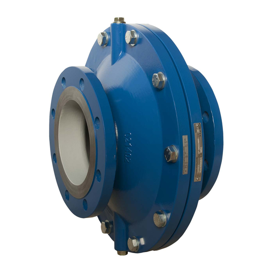
cashco 6A00 Instrucciones de instalación, uso y mantenimiento - Página 5
Navegue en línea o descargue pdf Instrucciones de instalación, uso y mantenimiento para Equipamiento industrial cashco 6A00. cashco 6A00 7 páginas. Inline deflagration flame arrestor
También para cashco 6A00: Manual de instalación, uso y mantenimiento (8 páginas)

V. MAINTENANCE
Attention: these works shall only be carried out by instructed qualified staff! All parts of the assembly kit A
(compare chapter VI) must be kept at hand.
As the operational conditions vary a lot, there is no temporal maintenance interval suggested. We
recommend to check the state of the flame arrestor every 6 month. Here not only the housing of the flame
arrestor but also the crimped metal ribbons shall be checked on impurity, corrosion and deformation. The
same applies to the resistance thermometer (additionally periodic function check) if present.
If a cleaning is planned the flame arrestor element (3) between the housings can be dismantled. Therefore,
the threaded bolt/screw nut (6, 7) shall be loosened. At minor impurity the flame arrestor is to be blown
out with compressed air or superheated steam in opposition to the operating direction of flow. In case of a
major impurity of the crimped metal ribbons the flame arrestor element may be rinsed with a cleaning
compound. Mechanical damages of the beading must be prevented! The exchange of the crimped metal
ribbons can be essential if the crimped metal ribbons have been damaged mechanically or chemically
(corrosion) or if more than 20% of the cross‐section area cannot be passed through after a cleaning. After
cleaning the flame arrestor shall be dried, the tight fit of the centre screw (8) shall be checked (compare
chart) and the flame arrestor shall be assembled in reverse order. It is recommended to exchange the
o‐rings (5).
The screws shall be fastened with the torques listed in the following chart.
Pos.
Mat.
DN20‐DN32
(¾"‐1¼")
CS
27
6, 7
SS
25
8
SS
12
CS = Carbon Steel, SS = Stainless Steel
After an explosion without or with stabilized burning at the flame arrestor it must be dismounted and
checked by instructed qualified staff! Depending on the explosion or combustion an exchange of the
crimped metal ribbon and the corresponding parts may be sufficient. However, considering the year of
manufacture the replacement of the complete instrument may often be the cheaper way. At flame
arrestors with resistance thermometers the functioning of the resistance thermometer shall be checked
after the maintenance. The reinstallation into the complete system is carried out according to chapter IV.
If it is necessary to replace single components of the flame arrestor, only original Cashco‐spare parts shall
be used.
04/16
Chapter V
DN40/DN50
DN65/DN80
(1½"/2")
(2½"/3")
54
45
12
25
Torques [Nm]
DN100
DN125/DN150
(4")
(5"/6")
93
230
80
185
45
185
DN200
DN250
DN300
(8")
(10")
(12")
465
800
400
680
400
680
Page 5
