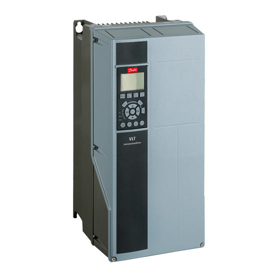
Danfoss VLT CDS 302 Manual de solución de problemas - Página 7
Navegue en línea o descargue pdf Manual de solución de problemas para Accionamientos de CC Danfoss VLT CDS 302. Danfoss VLT CDS 302 18 páginas. Compressor drives

Check List
Input power wiring
Output to motor
Grounding
Control wiring
Programming
Compressor Motor
Cable routing
Peripheral equipment
(sensors, contactors, etc)
Trip on over Temperature
Drive interior
EMC Precautions
Vibration
Environmental conditions
Proper clearance
Initial Trouble Shooting (visual inspection of the installation)
This list shows a variety of conditions that
should be inspected visually as a part of initial
troubleshooting.
Check for loose connections. Check for proper fusing. Check for blown fuses.
Check for loose connections. Check for switching
components in the output circuit. Check for
faulty contacts in the switch gear.
The drive requires a dedicated ground wire
from its chassis to the building ground. It is also
suggested that the motor be grounded to the
drive chassis. The use of conduit or mounting
Check for broken or damaged wires and
connections. Check the voltage source of the
signals. Though not always necessary depending
Check that the drive parameter settings are
correct according to the motor, application and
I/O configuration.
Check nameplate of the Compressor. Ensure the
compressor matches the drive. Check that drive's
ID
Name
113
Compressor Selection
Avoid routing motor wiring. AC line wiring and
signal wiring in parallel. If parallel routing is
unavailable, try to maintain a separation of 15-
Look for peripheral equipment such as switches
or input fuses circuit breakers that may be in the
input power side of the drive or output side of
the motor. Examine operation and condition of
Check the operational status of all cooling fans.
Check for blockage or constrained air passages.
Drive interior must be free of dirt, metal, chips,
moisture and corrosion. Check for burnt or
damaged power components or carbon deposits
that were the result of a disastrous component
Check for proper installation with regards to
electromagnetic capability. Refer to the CDS
manual, in the chapter "How to install" and then
Look for unusual amounts of vibration to which
the drive may be subject. The drive should be
Under specific conditions these units can
be operated within a maximum ambient
temperature of 50°C (24h average maximum
These drives require a top and bottom clearance
of 10cm to ensure proper airflow for cooling.
Display: Warnings, alarms, drive status; fault
history and many other items are available on the
local control panel of the drive.
of the drive to a metal surface is not considered
a suitable ground. Check for good grounding
connections that are tight and free of oxidation.
on the installation condition, the use of shield
cable or a twisted pair is recommended. Ensure
the shield is terminated correctly.
compressor par. 1-13 is set according to the
compressor e.g.:
Setup 1
Factory Setup
VZH117-R410A
VZH117-R410A
20cm between the cables or separate them with
a grounded conductive partition. Avoid routing
cables through free air.
these items as possible causes for operational
faults. Check function and installation of pressure
sensors or temperature sensors etc. used for
feedback to the drive.
failure. Check for cracks or breaks in the housing
of the power semiconductors or pieces of broken
components housing loose inside the unit.
" Electrical Installation – EMC Protection " for
further details.
mounted solidly or the use of shock mounts
employed.
45 °C). Humidity level must be less than 95%
non-condensing. Check for harmful airborne
contaminates such as sulphur based compounds.
Drives with exposed heat sinks out the back of
the drive must be mounted on a flat solid surface.
Unit
7
FRCC.PC.036.A2.02
