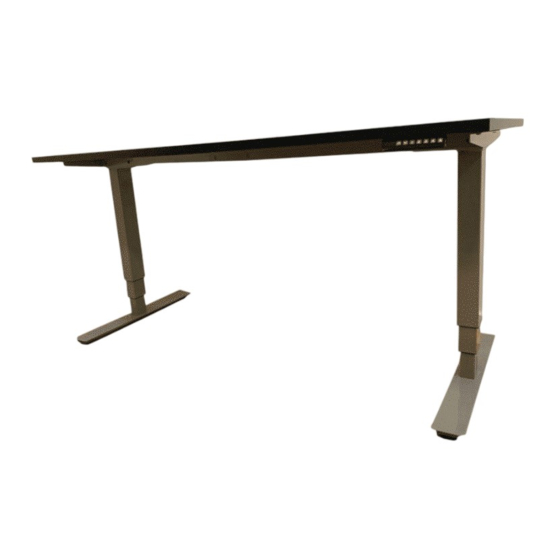
casiii STAND-35 Manual de instalación
Navegue en línea o descargue pdf Manual de instalación para Mobiliario interior casiii STAND-35. casiii STAND-35 2 páginas.

Item No.: STAND-35
Technical data
3
Column Stage
125KG
Max. Weight Capacity
580-1230mm
Height Range
1100-1900mm
Width Range
Component list
No.
Part
Qty No.
Part
Qty
1
2
2
2
Feet
Lifting Column
Qty No.
Qty
No.
Part
Part
3
1
4
1
Supporting Beam
Cable Management Tray
(Control Box included)
No.
Part
Qty No.
Part
Qty
1
5
6
2
Hand Switch
Side Bracket
(Option)
No.
Part
Qty
7
1
Power Plug
Installation guide
Accessory list
Attention: The drawings below are for guidance only and they may differ
slightly from the product and fittings received. Please contact our customer
service department should you have any queries.
Image
No.
Spec
A
M6
B
M6
C
M6
D
M6
E
St4.2
Allen Key
F
4x4mm
3
5
2
1
STEP 1
Install the Side Brackets
A
x4
F
4x4
Qty
4
5
4
8
12
STEP 2
Install the Lifting Columns
16
1
D
x8
F
4x4
2
F
D
Insert the lifting columns (2) into the ends of the supporting beam(4).
Fix the lifting columns using screws(D) with the Allen Key(F).
6
STEP 4
Install the Tabletop
E
1
x12
E
7
4
Attach the side brackets(5) to the ends of the supporting beam (4) using
screws(A) as show with the Allen Key(F).
A
STEP 3
C
x8
F
4x4
4
Place the feet(1) on the bottom of the lifting column(2).
Fix the feet using screws(C) with Allen Key(F).
E
The expansion distance of the
supporting beam can be adjusted
according to the actual use.
Attention: When the supporting beam is greater than 1720mm,
the installation method is as follows: Method 2 in Step 6.
F
A
5
Install the Feet
1
F
C
2
2
Loosen
F
4x4
Adjust
Tighten
