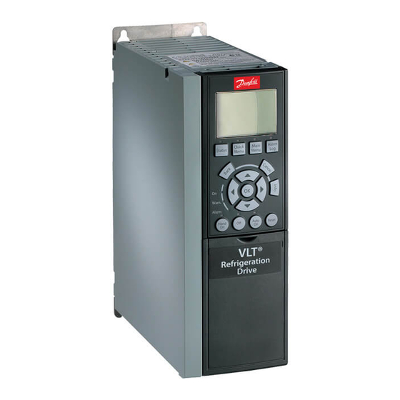
Danfoss VLT PROFINET MCA 120 Manual de instalación - Página 17
Navegue en línea o descargue pdf Manual de instalación para Media Converter Danfoss VLT PROFINET MCA 120. Danfoss VLT PROFINET MCA 120 18 páginas. Frequency converter
También para Danfoss VLT PROFINET MCA 120: Manual de instalación (8 páginas)

Index
Index
A
Abbreviation............................................................................................. 3
Additional resources.............................................................................. 2
Address switches..................................................................................... 9
Alarm......................................................................................................... 13
Alarm word............................................................................................. 13
Applying power.................................................................................... 12
Approvals............................................................................................. 0
C
Cable routing............................................................................................ 7
Cable specifications............................................................................. 10
Cabling requirements......................................................................... 10
Certifications....................................................................................... 0
Convention................................................................................................ 3
D
Discharge time......................................................................................... 4
E
Electrical installation........................................................................... 10
EMC interference..................................................................................... 7
EMC-compliant installation................................................................. 7
Exploded view.......................................................................................... 6
G
Grounding................................................................................................. 7
H
High voltage............................................................................................. 4
Host name................................................................................................. 9
I
Intended use............................................................................................. 2
Items supplied.......................................................................................... 2
L
Leakage current....................................................................................... 5
LED............................................................................................................... 3
Line topology........................................................................................... 8
Load sharing............................................................................................. 4
M
Module status........................................................................................ 13
Motor wiring............................................................................................. 7
MG90U402
Installation Guide
Mounting................................................................................................... 6
N
Network cabling.................................................................................... 12
Network status...................................................................................... 14
No communication with frequency converter.......................... 14
Q
Qualified personnel................................................................................ 4
R
Redundancy manager switch............................................................. 9
Ring/redundant line topology........................................................... 8
S
Safety........................................................................................................... 5
Screened cable.................................................................................. 7, 10
Star topology............................................................................................ 8
Symbol........................................................................................................ 3
T
Topology.................................................................................................... 8
U
Unintended start..................................................................................... 4
W
Warning.................................................................................................... 13
Warning 34.............................................................................................. 14
Warning word........................................................................................ 13
Wink command..................................................................................... 14
Wiring procedure................................................................................. 11
Danfoss A/S © Rev. 07/2014 All rights reserved.
15
