Duomo GS100M Manual - Página 3
Navegue en línea o descargue pdf Manual para Controlador Duomo GS100M. Duomo GS100M 12 páginas. 1 zone gas detection controller

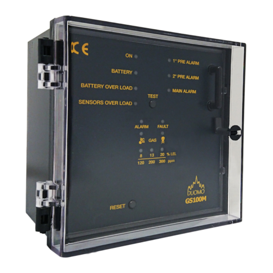
GS100M Fascia & PCB Layout
1
2
BATTERY
3
BATTERY OVERLOAD
SENSORS OVERLOAD
4
5
6
7
8
No
Description
1
ON
2
BATTERY
3
BATTERY OVERLOAD
4
SENSORS OVERLOAD
5
ALARM
6
TOXIC / EXPLOSIVE
7
PRE ALARM LEDS
8
RESET
9
TEST
10
1
PRE ALARM
st
11
2
PRE ALARM
nd
12
MAIN ALARM
13
FAULT
14
Supply & Relay Terminals
15
Sensor switch
16
Positive Safety switch
17
Main Alarm Relay actuation
18
Sensor/ Battery Terminals
t: 01905 797989
e: [email protected] | w: www.duomo.co.uk
9
ON
1 PRE ALARM
2 PRE ALARM
MAIN ALARM
TEST
ALARM
FAULT
GAS
8
13
20
% LEL
180
200 300
ppm
GS100M
LED illuminates when supply voltage is applied.
LED flashes during self diagnosis start up.
This LED illuminates when the GS100M is being poered by standby battery
LED Illuminated to indicate incorrect battery connection or high consumption during charging phase.
LED Illuminated to indicate short circuit or overload on sensor circuitry.
Indicates alarm status (explosive or toxix levels have been reached)
Toxic (Skull) LED illuminates when DIP switch for sensor is in CO (Toxic) position
Explosive LED illuminates when DIP switch for sensor is in GAS (Explosive) position
Indicate level of gas sensed (8 - 13 - 20% LEL / 120 - 200 - 300ppm)
When pressed resets the detector after an alarm or sensor fault condition.
When pressed checks the sequence and function of GS100M.
Press and hold to initiate a full function test, release once controller is in alarm state required
Will eventually activate all relays and their associated
Illuminates at 8% LEL (Explosive) or 120ppm (Toxic) gas concentration:
LED illuminates and the Pre Alarm relay 1 is actuated.
Illuminates at 13% LEL (Explosive) or 200ppm (Toxic) gas concentration:
LED illuminates and the Pre Alarm relay 2 is actuated.
Illuminates at 20% LEL (Explosive) or 300ppm (Toxic) gas concentration:
LED illuminates and the Main Alarm relay is actuated.
Indicates short circuit, sensor fault, loss of signal or incorrect sensor connection.
Electrical supply and relay connections. (See Wiring Schematic for connection instructions).
Used to enable or disable the sensor zone (ON/OFF) or determine type of gas to be detected (Toxic/Explosive)
- (See Configuring the GS100M section for setting instructions).
Positive Safety switch (See Configuring the GS100M section for setting instructions).
Determines if Main Alarm relay remains in position even if gas levels drop below alarm threshold.
(See Configuring the GS100M section for setting instructions).
Sensor and Battery (if fitted) terminals (See Wiring Schematic for connection instructions).
10
11
12
13
Ph
N
4
5
6
7
8
14
Purpose & Functionality
outputs.
3
ON
ON
1 2
1 2
9
10 11 12
1
2
3
4
5
6
7
15
16
17
18
