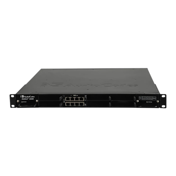
AudioCodes Mediant 4000B Manual de configuración rápida - Página 3
Navegue en línea o descargue pdf Manual de configuración rápida para Controlador AudioCodes Mediant 4000B. AudioCodes Mediant 4000B 10 páginas. Session border controller

Green On
Green Flashing
Yellow On
Yellow Flashing
Off
Red On
Off
Blue On
Off
Left
Green On
Ethernet
Green Flashing
Port
Off
Right
Orange On
Ethernet
Off
Port
4
(Slots 5 and 6) Figure shows unused chassis slots covered by slot covers. The slots can house one of
the following optional modules:
MPM module (only if an MPM module is also housed in slots 1 and 2). The MPM module
occupies two slots.
OSN server modules, where the OSN4 module is housed in Slot 5 and the HDMX module in
Slot 6. The OSN platform can be used to host third-party applications (e.g., IP PBX).
Note: The MPM and OSN modules are separate orderable items.
5
(Slots 7 and 8) Figure shows unused chassis slots covered by slot covers. The slots can house one of
the following optional modules:
MPM module (only if MPM modules are also housed in slots 1 and 2, and 5 and 6). The
MPM module occupies two slots.
Secondary HDMX module for the OSN server. The module is installed in Slot 7.
Note: The MPM and HDMX modules are separate orderable items.
6
Fan Tray module #2 with a schematic of the chassis' slot numbers and a STATUS LED Indicating
status of fan and Power Supply module #1. For LED descriptions, see Item #1 (above).
Mounting the Device
You can mount the device on a desktop using the four anti-slide rubber feet (supplied), which you need to stick
on the grooves located on the underside of the device.
You can also mount the device in a standard 19-inch rack, by placing it on a pre-installed rack shelf (not
supplied), and then securing it to the rack frame using front-mounting brackets (supplied). For additional 19-
inch rack mounting options, refer to the Mediant 4000B SBC Hardware Installation Manual.
Application running in Standalone state.
Application running in High-Availability (HA) Active state.
Application is starting bootup, or HA synchronization.
Application is running in HA Redundant state.
Booting up.
Out of service.
Normal operation.
Blue hot-swap LED indicating that the module can now be fully
extracted or inserted.
Note: Remove the module only if the LED is blue.
Module insertion process is complete.
Ethernet link established.
Data is being received or transmitted on the Ethernet port.
No Ethernet link.
1000Base-T Gigabit Ethernet link established.
No Ethernet link or 100Base-Tx link established.
3 |
P a g e
