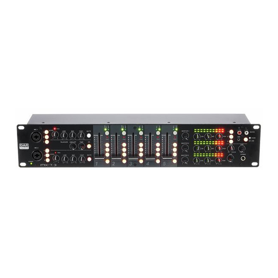
DAPAudio EM-7.2 Manual - Página 10
Navegue en línea o descargue pdf Manual para Equipo para DJ DAPAudio EM-7.2. DAPAudio EM-7.2 16 páginas. Professional
También para DAPAudio EM-7.2: Manual de instrucciones (12 páginas)

16. PFL
The PFL button (pre fade listening) is designed to route the channel input to the monitor section
independent of the individual channel's volume fader setting. It is possible to assign more than one
channel simultaneous to the PFL bus.
17. Channel Fader
A logarithmic 50mm fader, which controls the volume of it's channel. The faders should be positioned
within range of -12dB to 0dB, leaving you with sufficient room to allow precise matching of differences in
the channel's level settings. The overall volume is set with the master fader. Even though the channel
faders offer an additional gain of +6dB, it is better not to exceed the +0dB position by default.
22. Line In
Unbalanced RCA Line level input for connecting a line level device.
23. Rec Out
Unbalanced RCA Record output for connecting a recording device.
24. Master (Master 1, 2)
You can adjust the output signal to the Master Output (26).
12. Phono-Line 1 Indicator
Indicates that the Phono/ Line 1 input is selected.
13. Phono-Line 1 Indicator
Indicates that the Line 2 input is selected.
14. Selection Switch (Line 1/Line 2)
With this switch you can select between two sets of inputs
per channel.
15. Overload Indicator
The overload indicator shows peak levels in a channel's
incoming signal level. If the red overload LED frequently
Fig. 4
blinks or constantly lights, the corresponding channel is likely
to enter clipping and you have to reduce the input's
amplification using the corresponding gain (36-40) control
on the back. The overload LED lights at a level of 8 dB below
clipping. Make sure that the overload LED lights only briefly
during dynamic peaks.
18. Master (Master 1, 2)
You can adjust the output signal to the Master Output (26).
19. Ratio
Use this control to make a headphone mix between your PFL
and your master signal.
20. Output Signal VU Meter (Master 1, 2)
This meter is a multi-step LED. The accurate level indication
allows you to monitor the output signal level at anytime, and
match with other devices.
21. Line In Level
Controls the Line In level.
Fig. 5
8
