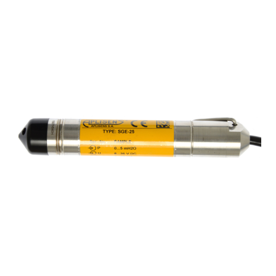
Aplisens SGE-25C Manual del usuario - Página 13
Navegue en línea o descargue pdf Manual del usuario para Accesorios Aplisens SGE-25C. Aplisens SGE-25C 20 páginas. Hydrostatic level probes
También para Aplisens SGE-25C: Manual del usuario (16 páginas)

C
9.3.2.
When the probe is in use the term "set range " is used.
The set range is the range whose lower end-point corresponds to an output current of 4mA and whose upper
end-point corresponds to a current of 20mA (or 20mA and 4mA respectively when the conversion curve
inverted). The set range may cover the whole of the basic range or only a part of it. The width of the set range
is the difference between the upper and lower limits of the set range. The probe may be set to any range
within the basic range of level values, subject the restrictions set out in the table in 5.1.
9.4. Configuration and Calibration.
9.4.1.
The SGE-25.SMART and SGE-25S.SMART probes has features which enable metrological and
identification parameters to be set and altered. The configurable metrological parameters affecting the probe's
output signal include the following:
a)
unit in which the measured level is expressed on the display
b)
upper end-point of the set range
c)
lower end-point of the set range
d)
time instant
e)
type of characteristic curve: linear or radical
Parameters of an informational nature which cannot be altered include the following:
f)
upper limit of the basic range
g)
lower limit of the basic range
h)
minimum set range
9.4.2
. Other identification parameters, not effecting the output signal, include: device address, device code,
factory identification code, factory device code, number of preambles (3÷20), UCS, TSD, program version,
electronics version, flags, factory number, label tag, description tag, date tag, message, record number,
sensing module number.
The process of setting the parameters listed in 9.4.1 and 9.4.2 is called "Configuration".
9.4.3.
It is possible to adjust the probe's zero point, for example to compensate for deviation resulting from a
change in position of installation.
The probes may also be calibrated, by taking readings with the input pressure controlled using a standard
device. This process and zero-point adjustment are called "Calibration".
9.4.4.
Configuration and Calibration of the probe are carried out using an Aplisens KAP communicator,
certain Hart communicators or a PC with Hart/RS232 converter and Aplisens Raport-01 software.
A description of the functions or the KAP communicator is contained in KAP Communicator Operating Manual,
and information on the Hart/RS232 converter can be found on the Hart/RS232/01 Converter information sheet.
A list of Hart protocol commands implemented for SGE-25.SMART, SGE-25S.SMART probes is
i
contained in the IO.HART operating instructions available at
After configuration it is important to protect the transducers using command HART [247].
During work transmitter should be safe prior to entries. This prevents accidental or intentional
changes configurational data. The protection function is accessible in KAP03 communicator,
"Raport's" software, as well as, in applying DD or DMT programs libraries.
10. INSPECTIONS, REPAIRS AND SPARE PARTS
10.1. Regular inspections.
10.1.1
. Regular inspections should be carried out in accordance with the regulations to which the user
subject
An inspection should be made of the external condition of the probe, during which:
- Check that there are no signs of mechanical damage in the form of impact marks or dents;
- Check the condition of the cable, which should not show signs of wearing, bending or fraying of the
external coating; check the condition of the packing gland.
Every two years or in accordance with regulations applicable to the user, check the zero point (4mA).
11
www.aplisens.pl
DTR.SG...04
(ENG)
1.
