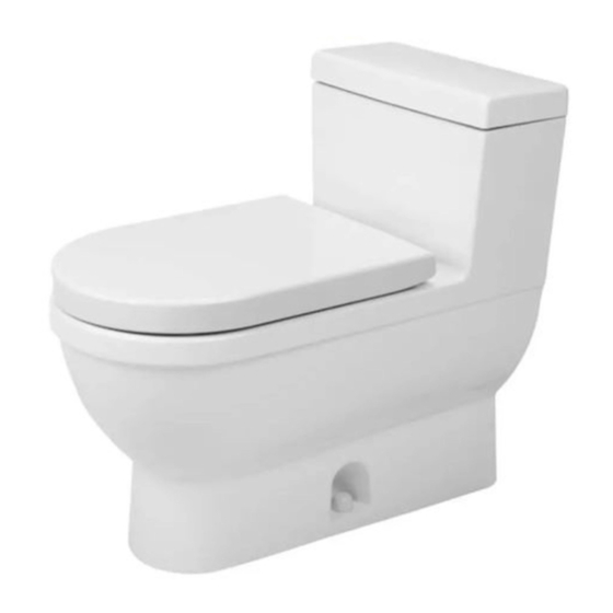
DURAVIT Starck 3 Instrucciones de montaje - Página 5
Navegue en línea o descargue pdf Instrucciones de montaje para Productos de fontanería DURAVIT Starck 3. DURAVIT Starck 3 12 páginas. Toilet seat and cover
También para DURAVIT Starck 3: Plantilla e instrucciones de montaje (2 páginas), Instrucciones de montaje (2 páginas)

Shut-off valve
Llave de paso
/
8
7
"
8
225 mm
/
4
7
"
8
125 mm
305 mm
12"
max. / máx.
/
1
" / 6,5 mm
4
1
INSTALLATION OF THE TOILET
Standard US installation dimen-
sions are indicated above.
1
The flange must not exceed
/
"/ 6.5
4
mm above the finished floor.
INSTALACIÓN DEL INODORO
Las
dimensiones
estándar
in-stalación para los Estados Uni-
dos están indicadas arriba.
La brida no debe sobresalir más de
1
/
" / 6.5 mm sobre el suelo acaba-
4
do.
1
/
"/6.5mm.
4
2
If the floor flange has not been se-
cured to the building structure affix
it accordingly using screws and fas-
teners.
Install the toilet bolts at the 3 and
9 o'clock position, equally spaced
from the finish wall.
Si la brida del inodoro no se ha ase-
de
gurado a la estructura de la edifi-
cación, fíjela debidamente usando
tornillos y sujetadores.
Coloque los pernos del inodoro en
las posiciones correspondientes a
las 3 y 9 horas, con igual separación
a la pared acabada.
3
9
3
Place the new wax-ring around the
outlet hole of the floor flange.
Coloque la nueva junta alrededor
del agujero de desagüe de la brida
en el suelo.
4
Connect the flexible water supply
line with the tank.
Conecte el tubo flexible de ali-
mentación de agua a la cisterna.
MAL_53758/14.02.2
5
