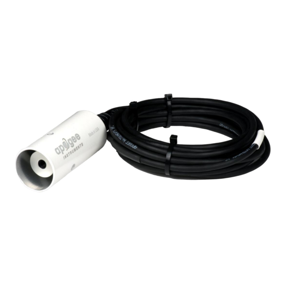
Apogee Instruments SI-4HR Manual del usuario - Página 11
Navegue en línea o descargue pdf Manual del usuario para Instrumentos de medida Apogee Instruments SI-4HR. Apogee Instruments SI-4HR 20 páginas. Infrared radiometer

OPERATION AND MEASUREMENT
All SI-100 series radiometers output two signals: a voltage from the thermopile radiation detector (proportional to
the radiation balance between target and detector) and a voltage from the thermistor (proportional to the
magnitude of the excitation voltage and resistance of thermistor). The voltage output from the thermopile is an
electrically-isolated bipolar (polarity is dependent on temperature difference between sensor and target) signal in
the microvolt range and requires a high resolution differential measurement. The voltage output from the
thermistor can be measured with a single-ended measurement. In order to maximize measurement resolution and
signal-to-noise ratio, the input range of the measurement device should closely match the output range of the
infrared radiometer. DO NOT connect the thermopile (white and black wires) to a power source. The detector is
self-powered and applying voltage will damage it. Only the red wire should be connected to a power source.
VERY IMPORTANT
: Apogee changed all wiring colors of our bare-lead sensors in March 2018 in conjunction
with the release of inline cable connectors on some sensors. To ensure proper connection to your data device,
please note your serial number or if your sensor has a stainless-steel connector 30 cm from the sensor head then
use the appropriate wiring configuration below.
Wiring for SI-100 Series with Serial Numbers 7283 and above or has a cable connector
Wiring for SI-100 Series with Serial Numbers range 0-7282
White: High side of differential channel (positive
thermopile lead)
Black: Low side of differential channel (negative
thermopile lead)
Green: Single-ended channel (positive thermistor lead)
Blue: Analog ground (negative thermistor lead)
Red: Excitation channel (excitation for thermistor)
Clear: Shield/Ground
White: Excitation channel (excitation for thermistor)
Black: Low side of differential channel (negative
thermopile lead)
Green: Single-ended channel (positive thermistor lead)
Blue: Analog ground (negative thermistor lead)
Red: High side of differential channel (positive thermopile
lead)
Clear: Analog ground (thermopile ground)
