Appalachian Stove & Fabricators UV-EF-MIL 30-P Manual de instrucciones de instalación y funcionamiento - Página 4
Navegue en línea o descargue pdf Manual de instrucciones de instalación y funcionamiento para Chimenea de interior Appalachian Stove & Fabricators UV-EF-MIL 30-P. Appalachian Stove & Fabricators UV-EF-MIL 30-P 11 páginas. Gas log heaters

GAS CONNECTION
CHECK GAS TYPE. Use only the gas type
indicated on the heater's rating plate. If the
gas listed on the plate is not the type of gas
supply DO NOT INSTALL. Contact your dealer
for proper model.
Always use an external regulator for all LP
appliances to reduce the supply tank pressure
to a maximum 13"WC. This is in addition to
the regulator fitted to the heater.
WARNING: Connection directly to an
unregulated LP tank can cause an explosion.
The normal gas connection is 3/8" made at
the left side facing the unit. If a right side
connection is required, the connecting pipe
may be lead behind the rear of the appliance
to terminate at the right hand side for
connection to the inlet of the appliance.
Test for leaks using a soap and water
solution after completion. DO NOT USE
OPEN FLAME.
GAS PRESSURE CHECK
Check the inlet pressure to the appliance
to ensure that it is as shown in the table
below. The minimum input can be obtained by
turning the adjustable control knob to its
lowest setting.
TABLE 1
MODEL
UVEF-MIL24,30N
GAS
NATURAL (N)
Max. Heat Input 39,000 BTUH
Min. Heat Input 23,000 BTUH
Gas Inlet Pressure
Max.
10.5 ins. WC
Ideal
7.0 ins. WC
Min.
4.5 ins WC
(Minimum for purpose of input adjustment only)
Regulator Pressure 3.5 ins WC
The pressure is controlled by the regulator
and should be checked at the pressure test
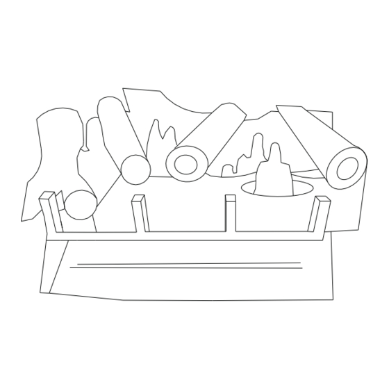
point located in the control valve body. Access
to the pressure test point is obtained by
removing all logs.
The pressure should be checked with the
appliance burning and the control set on high.
The pressure regulator is preset and
locked to avoid tampering. If the pressure is
not specified, replace the white replacement
part UV-001B for natural gas and UV-026B for
propane only.
After measuring the pressure, replace the
test point plug, ensuring no leaks, replacing
the heat shield where appropriate, and the
logs in their specified positions.
Pressure Test Point
Left
INSTALLATION AND CLEARANCES
fireplace, the following instructions must be carefully observed.
appliance to any combustible wall should not be less than 15".
42" from the top of the fireplace opening.
(model #1510-0140) may be used. Refer to figure 4B&4C on page 5
UVEF-MIL 24,30P
for a clear definition of clearances.
PROPANE (LP)
installing this gas appliance.
35,000 BTUH
23,000 BTUH
the chimney flue must be cleaned of soot, creosote, ashes, and
13.0 ins. WC
loose paint by a qualified chimney cleaner.
11.0 ins. WC
10.0 ins. WC
fireplace. Avoid any drafts that alter burner flame patterns.
10 ins. WC
burning fireplace only.
burner(s) clean may result in sooting and property damage.
operating, and unless other provisions are made for combustion air,
the screen shall have an opening for the introduction of combustion
air.
the appliance.
edge of the fireplace opening to a 2 ½"mantel is 28," 6" mantel is
38," and a 10" mantel is 44."
clearance from the top edge of the fireplace opening to a 2 ½"mantel
is 16," 6" mantel is 20," and a 10" mantel is 26."
from the top edge of the fireplace opening to a 2 ½"mantel is 18," 6"
mantel is 24," and a 10" mantel is 30."
shown in the figures on the next page.
(Section continued on following page)
To ensure safe installation into a masonry or factory built
1. Sidewall Clearances: The clearance from the side pf this
2. Ceiling Clearances: The ceiling height should not be less than
3. Mantel Clearances: In order to reduce clearances, a canopy
Important: Air openings shall not be obstructed in any way when
WARNING: Before installing in a solid fuel burning fireplace,
WARNING: Do not allow fans to blow directly into the
WARNING: This appliance is for installation in a solid fuel
WARNING: Failure to keep the primary air opening(s) of the
The fireplace screen must be in place when the appliance is
The left and right sides are determined when facing the front of
With no canopy used (Figure 4B) the clearance from the top
Without louvers and the canopy in position (Figure 4C) the
With louvers and canopy in position (Figure 4D) the clearance
The mantelpiece profile must fall within the cross section as
Right
FRONT OF BURNER
4
