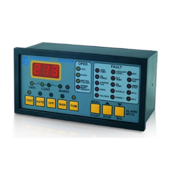
Datakom DKG-205 Manual del usuario - Página 6
Navegue en línea o descargue pdf Manual del usuario para Controlador Datakom DKG-205. Datakom DKG-205 20 páginas. Automatic mains failure unit

2) STOP RELAY: The relay will operate during programmed period in order to
stop the engine (Activate to Stop)
3) PREHEAT RELAY: The relay will operate the programmed delay before the
cranking of the engine. It will be deactivated during cranking and reactivated
during the rest period between cranks. It will be deactivated when the engine
runs.
4) CHOKE RELAY: The relay will operate the programmed delay before the
cranking of the engine. It will be deactivated when the engine runs.
12- CRANK OUTPUT: Engine crank output. Relay automatically turns off
when the alternator voltage reaches 100 volts or the alternator frequency
reaches 10Hz.
Relay contact rating is 10A/28V-DC.
13- FUEL OUTPUT: This output is used on engines equipped with a fuel
solenoid. The unit activates this output before starting the engine and
deactivates it to stop it. By programming, this relay can also control 'Activate
to Stop' type of engines.
Relay contact rating is 10A/28V-DC.
14- CHARGE INPUT: Connect the charging alternator's lamp output to this
terminal. If the charging alternator fails when the engine is running, the related
alarm indicator will turn on and the alarm output will be activated. This alarm
will not prevent the normal operation of the generating set.
15/16- BAT(+) / BAT(-): The positive (+) and negative (-) terminals of the DC
Supply shall be connected to these terminals. Be careful for the polarization, in
case of polarity error the unit will not operate. The unit operates on both 12V
and 24V battery systems.
17- PROGRAM LOCK INPUT: This input is used to prevent unwanted
modification to programmed values. If this input is left open, program values
can be modified via the front panel buttons, but if this input is connected to DC
Supply (-) it will not possible to change the program values.
18- LOW COOLANT LEVEL SWITCH: Connect the cooling radiator liquid
level switch to this input. This switch shall be negative closing in case of low
liquid level. This input has delayed sampling feature to prevent false detection.
19- SPARE-3 ALARM INPUT: Connect the spare alarm switch to this input.
The switch shall be negative closing type.
20- SPARE-2 ALARM INPUT: Connect the spare alarm switch to this input.
The switch shall be negative closing type.
21- SPARE-1 ALARM INPUT: Connect the spare alarm switch to this input.
The switch shall be negative closing type.
22- HIGH TEMPERATURE SWITCH: Connect the high temperature switch to
this input. This switch shall be negative closing switch type.
23- LOW OIL PRESSURE SWITCH: Connect the low oil pressure switch to
this input. The switch should be negative closing in case of loss of oil
- 6 -
