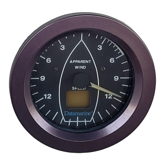
Datamarine Corinthian Series Manual del usuario - Página 7
Navegue en línea o descargue pdf Manual del usuario para Instrumentos de medida Datamarine Corinthian Series. Datamarine Corinthian Series 15 páginas. Wind machine

10
box
once
the mast
is stepped.
Once the necessary
cable
length is determined
(to
run to the mast
step
junction
box),
it should be
cut and
fed down the mast
from the masthead.
The bracket
should
be mounted
so
the grom-
meted hole
and
the rear
alignment pin
line up
with
the fore
/
aft axis
of
the
boat,
the
grommeted
hole
being
forward.
A
mounting
template is provided
in
the
back
of
this manual. The bracket may be
moved
slightly within the
confines
of the adjustment
slot
for
final positioning.
The
LX-360's
lower unit may be field adjusted to
compensate
for any masthead mounting angle. The
mounting bracket
should
be mounted horizontally
(shim
as needed)
as close
to the top
of
the mast as
possible.
An
"L" shaped
adapter bracket is provided
for mounting
on
the
side of
a mast if this is needed.
The remaining section
of cable should
be
installed
from the
final
location
of
the LX-360
and
run
to the
estimated
location
of
the
wiring
junction box.
Cable
length
is
not
critical and may
be
added
to
or
trimmed
as necessary.
If
needed on
a particular
installation,
Datamarine
can provide a cable connector
to
use
in
place of
the
junction box. Wire
color and pin connections are
provided
below.
A 120'
cable (Model
WX-177)
is also
available.
Pin#
1
2
3
4
Color
White
Red
Green
Black
Pin#
5
6
7
8
Color
Blue
Yellow
Shield
Not connected
•
I
w
~
~
w
~
~
CABLE
FROM
MASTHEAD
COVER
~
ID
1
2
1
~
1~
1
~
ID
~
~
~
m
>
m
~
~
~
JUNCTION BOX DETAIL
0
0
CABLE
TO INSTRUMENT
Mount
the junction box
in
a
dry,
convenient
location
and,
once
the mast is
stepped,
run both
cut
ends of
the
wire into it.
Install the
spade
lugs pro-
vided and connect
to the terminal
strip (red
to red,
white to
white,
etc.) as shown
on figure 4.
This
completes
the
wiring
required to
connect
the
masthead unit
to the LX-360. To
complete
the
installation
,
connect
the
cable
from the junction box
to the
LX-360
as shown
in figure
3.
TE:
Make sure a// wires (including
the
shield)
are
l,Dnnected
in the Junction Box. This will assure
proper operation of your
LX-360.
Figure
4
11
