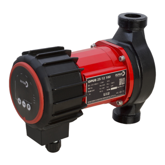
DUYAR OPUS 2-6 180 Instalación Funcionamiento y mantenimiento - Página 7
Navegue en línea o descargue pdf Instalación Funcionamiento y mantenimiento para Caldera DUYAR OPUS 2-6 180. DUYAR OPUS 2-6 180 18 páginas.

INSTALLATION, OPERATION, MAINTENANCE
1. Check the phase and neutral ends of the network.
2. Attach an appropriate diameter insulated ferrule to
the ends of the electrical wires.
3. Remove the plugs at the top of the unions.
4. Unscrew the junction box and remove the box.
Figure 6.8: Removing the junction box
5. Transmit the ends of the cable through the number
1 gland shown in the figure.
6. Make the electrical connection of the transmitted
cable to the socket named "A" in Figure 6.9 as shown
in Figure 6.7.
7. Tighten the glands so that there is no excessive cable
tension at the connection point.
8. Reinstall the junction box.
Figure 6.8: Removing the junction box
The electrical cable of the pump must not
come into contact with the pump or the
plumbing.
Mains voltage values must be within the
values in Table 5.1.
It is recommended to use a residual current relay to
protect the user and the pump. Whichever type of
pump is to be used, it must be selected according to
the nominal current and voltage of that pump, and a
B type relay (which can open at DC current and high
frequency). (Grounding current should be below 3.5
mA according to EN 60335 standard.)).
AND REPAIR MANUAL
OPUS SERIES
7. DISPLAY AND SETTINGS
The OPUS display consists of nine LEDs and three
control keys. See. Figure 7.1.
The control screen provides information about the
pump status and allows the desired operating mode
to be set. Indicators and keys on the control screen are
as given below:
1. Automatic Variable Pressure Operating Mode
2. Automatic Constant Pressure
Operating Mode
3. Manual Operating Mode
4. Night Operating Mode
5. Power Drawn
6. Target Pump Head
7. Motor Output Voltage
8. Target Speed
9. For Program Selections and Settings
10. Minus Key To Decrease
11. Plus Key To Increase
5
