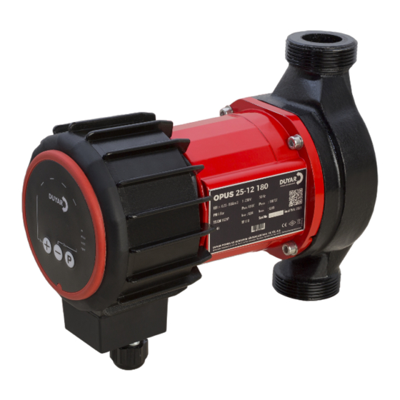
DUYAR OPUS 40-10 220 C Instalación Funcionamiento y mantenimiento - Página 9
Navegue en línea o descargue pdf Instalación Funcionamiento y mantenimiento para Caldera DUYAR OPUS 40-10 220 C. DUYAR OPUS 40-10 220 C 18 páginas.

INSTALLATION, OPERATION, MAINTENANCE
9. OPERATING MODES AND
SELECTION CRITERIA
OPUS circulation pumps, with their ECM technology,
provide operating modes that act in accordance with
the variable flow requirement.
OPUS Operating Modes
Manual
Constant pressure
As the working point of the pump shifts to the left, that is,
İzolasyon Vanası
the flow rate decreases, the following occurs:
►
In manual mode, the head is increased.
In constant pressure operation mode, the speed
►
decreases and the head remains constant.
In variable pressure operating mode, the rotation
►
speed decreases linearly so that the head drops to half
of the set head value.
9.1 Manual Operating Mode
Flow Q (m3/h)
İzolasyon Vanası
Figure 9.2: Manual Operation Mode Display
In this operating mode, the pump operates at the set
rotation speed. The desired speed can be selected.
AND REPAIR MANUAL
Variable p ressure and constant
pressure
operating m
provide energy s avings b y
following curves according to the
variable load requirement of the
system.
Flow Q (m3/h)
9.2 Constant Pressure Operating Mode
H
setting
Figure 9.3: Constant Pressure Operating Mode Display
In this operating mode, the pump operates by changing
the rotation speed so that the set pump head (Hsetting)
odes
remains constant.
The Hsetting value of the pumps selected in accordance
with the operating point is determined as follows:
The H value at the operating point is marked on the
►
constant pressure operating mode graph.
►
If the marked point is on any operating mode curve
belonging to a multiple of 0.5, the H value of that
operating mode curve is accepted as the Hsetting value.
►
If the marked point is not on any operating mode
curve belonging to 0.5 multiples, the nearest operating
mode curve is passed and the H value of that curve is
accepted as the Hsetting value.
The operating mode curves are plotted on the graph
at 1 meter intervals. The setting can be selected on the
screen in 0.5 meter increments.
9.3 Variable Pressure Operating Mode
H
setting
H
/2
setting
Figure 9.5: Variable Pressure Operating Mode Display
OPUS SERIES
Flow Q (m3/h)
Şekil 4.2.4 B
Flow Q (m3/h)
7
