4next EasyNET Inicio rápido
Navegue en línea o descargue pdf Inicio rápido para Cables y conectores 4next EasyNET. 4next EasyNET 2 páginas.
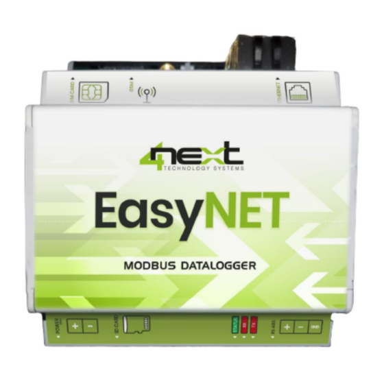
EasyNET
Quick Start
1. Cabling and connections
Wiring and installation of EasyNET are very simple.
This guide briefly explains how to make the electrical connections and settings for initial access.
1.1 SD Card
EasyNET stores the data on a standard "SD card". Insert the SD card with the slats facing the screen-
printed part, as shown in Fig.1.
The connector type is push-push: to insert, press until you hear a click.
To remove the SD card, press lightly; when you hear a click, the card will lift up and it can be removed.
We always recommend the use industrial SD cards.
Fig.1 SD Card insertion
1.2 Serial
If using serial to read data from ModBus RTU devices, connect the RS485 wires as shown
below:
Fig.3 Ethernet connector
1.4 Power supply
Connect EasyNET to a 10-32 Vdc power supply as in Fig.4.
There is no polarity to be respected.
2. Access and configuration
EasyNET has an integrated WEB server, so it can be configured using a standard browser. To access the configuration pages, enter
the EasyNET IP address in the browser of your PC, tablet or smart phone.
The device from which the connection is made must be within the same network as EasyNET (Par. 2.1).
2.1 Network IP address
The default IP address of EasyNET is 192.168.1.100.
If your network is of the same IP class: 192.168.1..., go to section 2.3,
otherwise follow the instructions from section 2.2 to set the correct IP
address.
To identify the IP class of your network, run the command IPCONFIG from
the command prompt.
In Fig.5, the IP address of the PC is 192.168.1.5. It belongs to the
same class/network as EasyNET, since the first 3 numbers
(192, 168 and 1) are the same. You can therefore reach EasyNET
from the PC browser.
1.3 Ethernet
If an Ethernet connection is used to read data from ModBus TCP devices, insert the Ethernet cable
jack into the RJ connector of the EasyNET, as shown in Fig.3.
Fig.2 RS485 connector
Fig.4 Power connection
Fig.5 Checking the IP address of your PC