COOK Gemini 100 Series Manual de instalación, uso y mantenimiento - Página 3
Navegue en línea o descargue pdf Manual de instalación, uso y mantenimiento para Ventilador COOK Gemini 100 Series. COOK Gemini 100 Series 8 páginas. Ceiling and cabinet fans
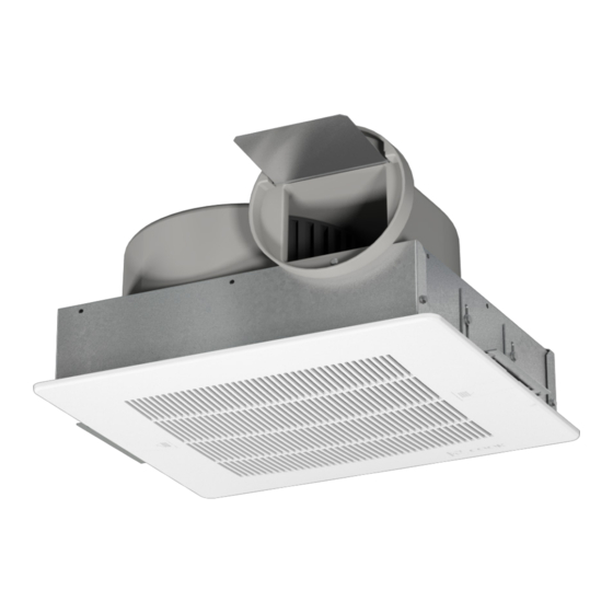
Typical Installation
Roof
Joists
Power
cord
Seal around the
unit with caulk.
Insulation around unit.
Also, cover the fan with insulation.
Figure 2
Unit Housing
Grate Protrusion
Notice! Do not install above or around
cooking equipment (shaded area)
45
O
Wiring Installation
All wiring should be in accordance with local ordinances
and the National Electrical Code, NFPA 70.
GEMINI IO&M
Roof jack with damper
or roof cap
6" round duct. Insulated duct will help
absorb vibration. Use the shortest runs
possible & long radius elbows.
Short (1') piece of flexible duct
will absorb vibration & noise.
Joists
Mounting
Bracket
(aluminum grille only)
Filter (optional)
45
O
Cooking
Equipment
Floor
or
Ensure the power supply (voltage, frequency and current
carrying capacity of wires) is in accordance with the motor
nameplate. Refer to Wiring Diagrams.
Lock out all power sources before unit is wired to power
source.
Follow the wiring diagram in the disconnect
switch and the wiring diagram provided with the
motor. Correctly label the circuit on the main
Ceiling
power box and always identify a closed switch
to promote safety (i.e., red tape over a closed
switch).
Grille
Note: Insulate Unused Leads. Fan plug box is designed
for single speed operation, using an FSC to vary speed if
required. Do not wire to more than two leads.
Wiring Diagrams
Gemini 100 Series:
White Wire
(Common)
For fan power supply connection use 4-wire cable
provided in field wiring box shown on above diagram.
3
Exterior
Wall
Use foil tape
on the joints
to ensure a
good seal.
Wall cap
with damper
Cap off wire that is not in use.
Red Wire (Low Speed)
Black Wire (High Speed)
Green Wire
(Ground by COOK)
Ground Screw for
Field Grounding
B51111-002