Bresser Meteo TP Colour Manual de instrucciones - Página 8
Navegue en línea o descargue pdf Manual de instrucciones para Estación meteorológica Bresser Meteo TP Colour. Bresser Meteo TP Colour 16 páginas. Digital rc alarm clock
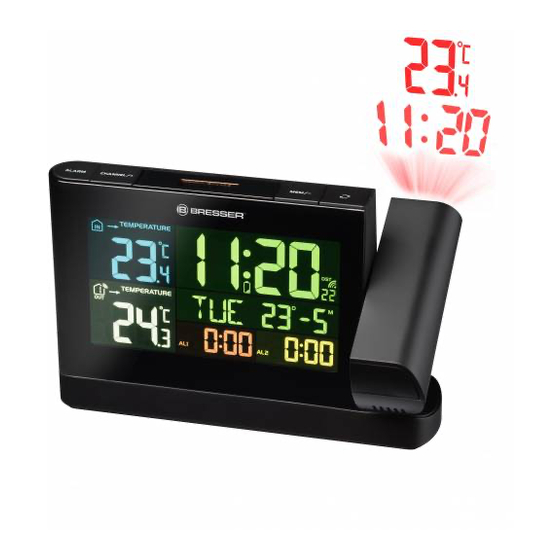
1 Symbol indoor area
3 Alarm symbol for defined low temperature (in-
door)
5 AM/PM information in 12-hour time mode
7 Battery level indicator (base device)
9 Daylight saving time (DST)
11 Current time (seconds)
13 Month (M)
15 Alarm time (hours)
17 Symbol for alarm time 2
19 Temperature value (outdoor)
21 Ice warning
23 Symbol outdoor area with channel display
25 Temperature unit (°C or °F selectable)
7 Before starting operation
NOTICE
Avoid connectivity disruptions!
To avoid connectivity disruptions between the devices, consider the following points before starting
operation.
1. Place base station (receiver) and remote sensor (sender) together as close as possible.
2. Set up power supply for the base station and wait until the indoor temperature is displayed.
3. Set up power supply for the remote sensor.
4. Position the base station and the remote sensor within the effective transmission range.
5. Ensure that the base station and remote sensor are assigned to the same channel.
When changing batteries always change batteries in the main unit as well as all remote units and re-
place them in the correct order, so the remote connection can be re-established. If either of the
devices is mains-powered, the power supply must be disconnected for a short moment also for this
device when exchanging the batteries. If batteries are exchanged in only one of the devices (i.e. the
remote sensor) the signal can't be received or can't be received correctly.
Note, that the effective range is vastly affected by building materials and position of the main and re-
mote units. Due to external influences (various RC devices and other sources of interference), the
maximum distance can be greatly reduced. In such cases we suggest to position the main unit and the
remote sensor at other places. Sometimes all it takes is a relocation of one of these components of a
few inches! Though the remote unit is weather proof, it should be placed away from direct sunlight,
rain or snow.
8 Setting up power supply
Base device
1. Insert the DC connector into the connection socket of the base station.
2. Insert the mains plug into the power outlet.
3. The device is energized directly.
4. Wait until the indoor temperature is displayed on the base station.
8 / 16
2 Temperature trend (indoor) (rising, steady or
falling)
4 Alarm symbol for defined high temperature (in-
door)
6 Current time (hours)
8 Current time (minutes)
10 Symbol for radio signal
12 Day (D)
14 Alarm time (minutes)
16 Alarm symbol (bell)
18 Weekday
20 Symbol for highest (MAX) or lowest (MIN)
value
22 Battery level indicator (remote sensor)
24 Temperature value (indoor)