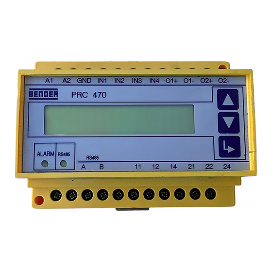
Bender B95 012 004 Manual - Página 3
Navegue en línea o descargue pdf Manual para Controlador Bender B95 012 004. Bender B95 012 004 20 páginas. Control and indicating device for ems and eds systems

Maßbild
Abb. 2: alle Maße in mm
Anschluss
Schließen Sie das Gerät entsprechend dem Anschlussplan in der
Anleitung des RCMS-Systems an. Beachten Sie dabei das Anzugs-
drehmoment für die Klemmschrauben (siehe Technische Daten).
Anschlüsse
Legende zum Anschlussschaltbild
1
Steuerungseingänge EDS470 (EDS473) für Systemstart
2
Anschluss für externe Reset-Taste
3
Anschluss für externe Prüftaste
Anschluss für Prüfgerät PGH470.., wird nur bei EDS-Systemen eingesetzt,
4
um den zur Erdschlusssuche im IT-Netz notwendigen Impuls gegen Erde zu
liefern.
Alarmrelais schalten, wenn ein Ansprechwert über- oder unterschritten
5
wird (Sammelmeldung).
F
Sicherung(en) Speisespannung
108001 / 11.2004
siehe Typenschild
see nameplate
(+)
U S
(-)
F
6A
A1 A2
GND IN1 IN2 IN3
A1
A2 GND IN1 IN2 IN3 IN4 O1+ O1- O2+ O2-
PRC470
ALARM
RS485
A
B
BMS
RCMS470...,
SMO..., EDS47x
Dimension diagram
Connection
Connect the device in accordance with the wiring diagram in the
manual that comes with the RCMS system. Please observe the
tightening torque for terminal screws (see Technical data).
Connections
1
2
3
Prüfgerät PGH470
(nur bei EDS470-Systemen)
Test device PGH470
(only for EDS470 systems)
IN4
O1+ O1- O2+ O2-
V. 2.x
2
RS485
A
B
11
12
14
21 22
11
12 14
22 24
Legend to the wiring diagram
1
Control inputs EDS470 (EDS473) for system start
2
Connection for external Reset key
3
Connection for external Test key
Connection for testing device PGH470.., is only applied with EDS systems in
4
order to provide the necessary impulse against earth for insulation fault
location in IT systems.
Alarm relays switch when the residual current exceeds or falls below the
5
set response value (common alarm)..
F
Fuse(s) supply voltage
PRC470, PRC470E
Figure 2: All dimensions in mm
4
24
21
5
3
