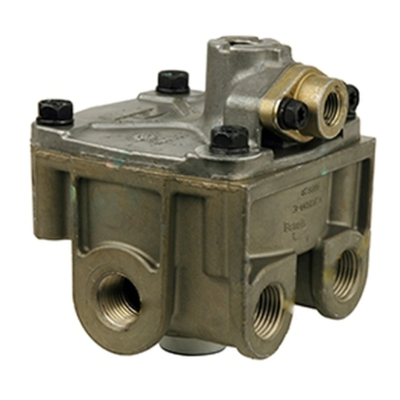
BENDIX ATR1DC ANTILOCK TRACTION RELAY Manual - Página 5
Navegue en línea o descargue pdf Manual para Unidad de control BENDIX ATR1DC ANTILOCK TRACTION RELAY. BENDIX ATR1DC ANTILOCK TRACTION RELAY 12 páginas. Antilock traction relay valve
También para BENDIX ATR1DC ANTILOCK TRACTION RELAY: Instrucciones de instalación (4 páginas)

EC-16
™
OR EC-17
™
CONTROLLER
SOLENOID
CONNECTOR
BLEND BACK
PISTON
DOUBLE
CHECK VALVE
"B"
RELAY PISTON
SUPPLY PORT
INLET-EXHAUST
FIGURE 8 - TRACTION CONTROL BRAKE APPLICATION
slightly allowing the inlet valve to return to its seat. The
exhaust valve remains closed. With both the inlet and
exhaust valves closed, air pressure in the brake chambers
is held constant and neither increases nor decreases.
SERVICE BRAKES - RELEASING
When the brake application is released, air from above the
relay piston, flows back to and past double check valve "B"
and returns to the exhaust of the brake valve. Air on the
other side of double check valve "B" and from double check
valve "A" also returns to the exhaust of the brake valve. As
air pressure above the relay piston is released the natural
resilience of the relay piston drain valve causes it to return
to its original position which opens the drain passage in the
relay piston. With the piston drain open, gravity allows
contamination to flow out the relay valve exhaust.
As air pressure is reduced above the relay piston, pressure
beneath lifts the piston away from the exhaust valve and
opens the exhaust passage. Air from the service brake
chambers returns to the ATR-1DC
open exhaust.
SERVICE BRAKES – APPLYING (PRIMARY CIRCUIT
FAILED)
In the event the rear axle delivery line from the brake valve is
broken, air from the brake valve's front axle delivery circuit
will enter the secondary control port. Secondary control
pressure flexes double check valve diaphragm "A" causing
it to seal the air passage leading to the solenoid and opening
the passage leading to double check valve "B". Double check
TRACTION CONTROL SOLENOID
EXHAUST PORT
VALVE
™
valve and flows out the
SECONDARY
SERVICE PORT
PRIMARY
SERVICE PORT
DOUBLE
CHECK VALVE "A"
DELIVERY
PORT
valve diaphragm "B" flexes in response to secondary control
pressure and seals the air passage leading to the primary
control port and primary delivery circuit of the brake valve.
Air flows past double check valve diaphragm "B" and through
a passage in the cover to the top of the service relay piston.
In response to air pressure, the relay piston drain valve flexes
and seals the drain passage leading to the relay exhaust.
Simultaneously the relay piston moves into contact with the
exhaust portion of its inlet and exhaust valve. With the
exhaust passage sealed, continued movement of the piston
unseats the inlet portion of the inlet and exhaust valve,
allowing supply air from the reservoir to flow out the ATR-1DC
valve's delivery ports to the brake chambers.
TRACTION CONTROL - SERVICE APPLICATION
GENERAL
While under the control of an antilock traction controller, the
™
ATR-1DC
valve's solenoid is able to initiate a brake
application that allows the traction system to control wheel
spin during acceleration under 25 mph. When wheel spin is
detected and the vehicle is stopped, or moving at any speed
up to 25 mph, the antilock traction controller instantly
energizes the solenoid in the ATR-1DC
applies air to each of the rear axle modulators as shown in
Figure 8. The modulators are also equipped with solenoid
valves and because the controller also controls them, the
solenoid valves in the appropriate modulator are opened and
closed to gently pump the brake on the spinning wheel only.
This brake application, to the spinning wheel, forces the
differential to drive the stationary or slowly spinning wheel.
BRAKE VALVE
(SHOWING
DELIVERY AIR
LINES ONLY)
AIR BAG
BRAKE
CHAMBER
WHEEL SPEED
TONE RING
SENSOR
™
valve which then
™
5
