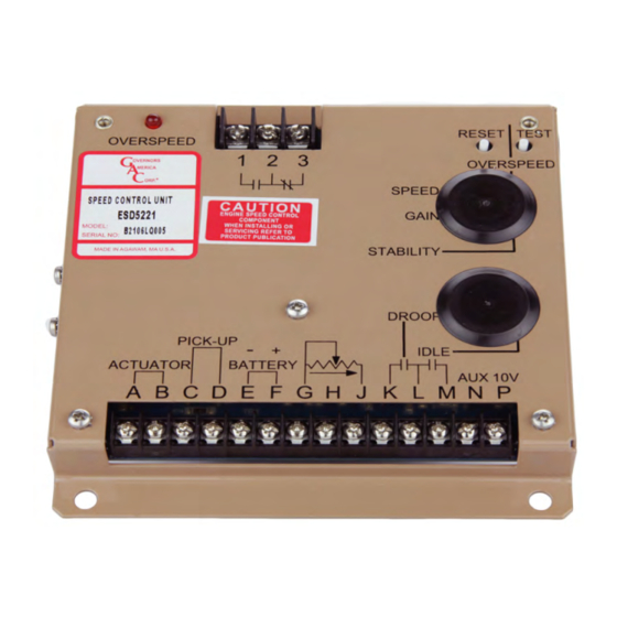
GAC ESD-5550 Series Manual - Página 7
Navegue en línea o descargue pdf Manual para Unidad de control GAC ESD-5550 Series. GAC ESD-5550 Series 8 páginas. Speed control unit
También para GAC ESD-5550 Series: Información técnica (12 páginas), Manual (8 páginas)

6
METHODS OF OPERATION
One of two methods of operation for the ESD5550/5570 may now selected; starting at operating speed, or starting at idle.
STarTInG aT oPeraTInG SPeeD
1.
Remove the connection between Terminals M & G.
2.
Start the engine and accelerate directly to the operating
speed (Gen Sets, etc.).
3.
Adjust the SPEED RAMPING for the least smoke on acceler-
ation from idle to rated speed.
4.
If the starting smoke is excessive, the STARTING FuEL may
need to be adjusted slightly CCW.
5.
If the starting time is too long, the STARTING FuEL may need
to be adjusted slightly CW.
7
SySTEM TROUblESHOOTINg
InSUffIcIenT maGneTIc SPeeD SIGnaL
A strong magnetic speed sensor signal eliminates the possibility of missed or extra pulses. The speed control unit governs well with 0.5
volts RMS speed sensor signal.
A speed sensor signal of 3 volts RMS or greater at governed speed is recommended. Measurement of the signal is made at Terminals
C and D.
The amplitude of the speed sensor signal can be raised by reducing the gap between the speed sensor tip and the engine ring gear. The
gap should not be any smaller than 0.02 in (0.5 mm). When the engine is stopped, back the speed sensor out by 3/4 turn after touching
the ring gear tooth to achieve a satisfactory air gap.
SYSTem InoPeraTIve
If the engine governing system does not function, the fault may be determined by performing the voltage tests described in Steps 1
through 4. Positive (+) and negative (-) refer to meter polarity. Should normal values be indicated during troubleshooting steps, and then
the fault may be with the actuator or the wiring to the actuator. Tests are performed with battery power on and the engine off, except where
noted. See your actuator publication for troubleshooting testing.
STeP
WIreS
cHecK
1
F(+) & E(-)
Battery Supply
Voltage
(12 or 24 V DC)
2
C(+) & D(-)
1.0 V AC RMS
minimum while
cranking
3
P(+) & G(-)
10 V DC, Internal
Supply
4
F(+) & A(-)
1.0 - 2.0 V DC while
cranking
1.
DC battery power not connected. Check for blown fuse.
2.
Low battery voltage
3.
Wiring error
1.
Gap between speed sensor and gear teeth too great. Check Gap.
2.
Improper or defective wiring to the speed sensor. Resistance between D and C should be 160 to
1200 Ω. See specific mag pickup data for resistance.
3.
Defective speed sensor.
1.
Short on Terminal P.
2.
Defective speed control unit.
1.
SPEED parameter set too low
2.
Short/open in actuator wiring
3.
Defective speed control
4.
Defective actuator, see your actuator's Troubleshooting guide.
7
STarTInG aT IDLe SPeeD
This method separates the starting process so that each may be
optimized for the lowest smoke emissions.
1.
Replace the connection between Terminals M & G with a
switch, usually an oil pressure switch.
2.
Start the engine and control at an idle speed for a period of
time prior to accelerating to the operating speed.
3.
If the starting smoke is excessive, the STARTING FuEL may
need to be adjusted slightly CCW.
4.
If the starting time is too long, the STARTING FuEL may need
to be adjusted slightly CW.
5.
When the switch opens, adjust the SPEED RAMPING for the
least amount of smoke when accelerating from idle speed to
rated speed.
ProBaBLe caUSe
ESD5550-5570 Series Speed Control Unit 9-2020-E PIB1003
Governors America Corp. © 2020 Copyright All Rights Reserved
