GAC ESD5151 Manual de inicio rápido - Página 4
Navegue en línea o descargue pdf Manual de inicio rápido para Unidad de control GAC ESD5151. GAC ESD5151 6 páginas. Speed control unit
If the engine governing system does not function, the fault may be determined by performing the voltage tests described
in Steps 1 through 4. Positive (+) and negative (-) refer to meter polarity. Should normal values be indicated during trouble-
shooting steps, and then the fault may be with the actuator or the wiring to the actuator. Tests are performed with battery
power on and the engine off, except where noted. See actuator publication for testing procedure on the actuator.
Step
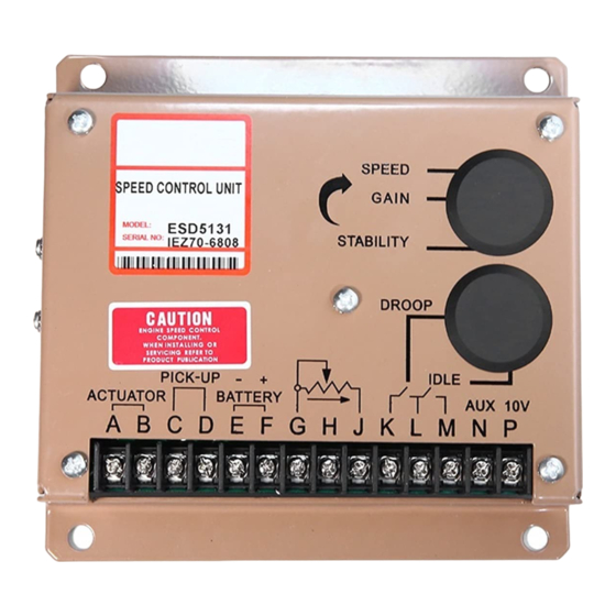
teRminAlS
1
F(+) & E(-)
2
C & D
3
P(+) & G(-)
4
F(+) & A(-)
If the governing system functions poorly, perform the following tests.
Symptom
Engine overspeed
Overspeed shuts down engine after run-
ning speed is reached.
Overspeed shuts down engine before
running speed is reached.
Actuator does not energize fully while
cranking.
Engine remains below desired governed
speed
noRmAl ReADing
Battery Supply Voltage
(12 or 24 VDC)
1.0V AC RMS min. while cranking
10V DC, Internal Supply
1.0 - 2.0V DC while cranking
Unsatisfactory Performance
1. Do Not Crank. Apply DC power to the
governor system.
2. Manually hold the engine at the desired
running speed. Measure the DC voltage
between Terminals A(-) & F(+) on the
speed control unit.
1. Check impedance between Terminals C &
D. Should be 30 to 1200 ohms.
1. Measure the voltage at the battery while
cranking.
2. Momentarily connect Terminals A and F.
The actuator should move to the full fuel
position.
1. Measure the actuator output, Terminals A &
B, while running under governor control.
This document is subject to change without notice.
Caution: None of GAC products are flight certified controls including this item.
System Inoperative
pRobAble CAuSe of AbnoRmAl ReADing
1. DC battery power not connected. Check for blown fuse
2. Low battery voltage.
3. Wiring error
1. Gap between speed sensor and gear teeth too great. Check gap.
2. Improper or defective wiring to the speed sensor.
Resistance between D and C should be 30 to 1200 ohms.
3. Defective speed sensor.
1. Short on Terminal P. (This will cause a defective unit.)
2. Defective speed control unit
1. SPEED adjustment set too low.
2. Short/open in actuator wiring.
3. Defective speed control.
4. Defective actuator. See Actuator Troubleshooting.
teSt
1. Actuator goes to full fuel. Then disconnect speed sensor
1. If the voltage reading is 1.0 to 2.0 VDC,
2. If the voltage reading is above 2.0 VDC, actuator or
3. Set point of overspeed shutdown device set too low.
4. If the voltage reading is below 1.0 VDC, defective speed
1. Speed adjustment set too high.
2. OVERSPEED set to close to running speed.
3. Actuator or linkage binding.
4. Speed control unit defective.
1. OVERSPEED set too low. Adjust 5-6 turns CW.
2. Erroneous speed sensor signal. Check wiring.
1. If the voltage is less than 7V for a 12V system, or 14V
1. Actuator or battery wiring in error.
2. Actuator or linkage binding.
3. Defective actuator.
4. Fuse opens. Check for short in actuator or harness.
1. If voltage measurement is within 2 volts or more of the
2. Speed setting too low.
4
pRobAble fAult
at Terminal C & D. If actuator still at full fuel-speed con-
trol unit defective. If actuator at minimum fuel position,
erroneous speed signal. Check speed sensor cable.
a) SPEED adjustment set above desired speed
b) Defective speed control unit.
linkage binding.
control unit.
for a 24V system, check or replace the battery.
battery supply voltage level, then fuel control restricted
from reaching full fuel position. Possibly due to mechani-
cal governor, carburetor spring, or linkage interference.
PIB1000 C