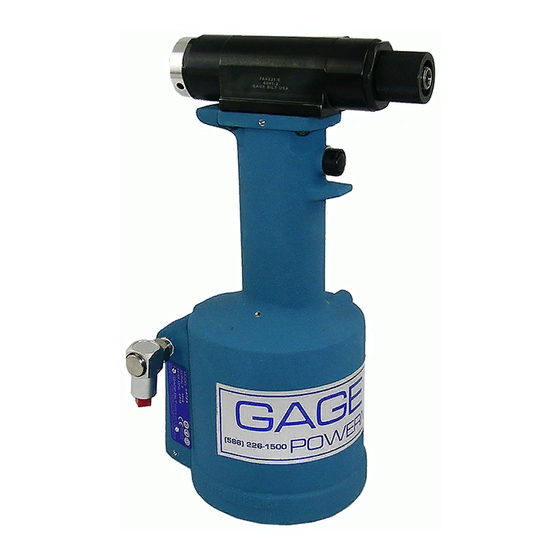
Gage Bilt GB784 Instrucciones de instalación - Página 12
Navegue en línea o descargue pdf Instrucciones de instalación para Herramienta eléctrica Gage Bilt GB784. Gage Bilt GB784 13 páginas.

SETTING THE SHIFT POINT:
The shift point must be adjusted to ensure the flushness of the rivet stem after installation. To Adjust:
1. Connect the tool to a clean dry air source of 90 psi to 100 psi. Remove nut.
2. Hand tighten small end of 784159 gage onto piston.
3. Depress trigger and hold. Gage point #1 should line up with face of front cap as shown. Release
trigger.
4. To increase gage protrusion turn adjuster knob clockwise or counter-clockwise to decrease gage
protrusion. Tool must be rechecked after making adjustments.
NOTE: Adjustment can only be made by one-half turn in either direction.
CAUTION: Trigger must be released before turning adjuster knob.
GAGE POINT #3
GAGE POINT #2
GAGE POINT #1
784159 - SETTING GAGE
SHIFT PISTON CHECK:
The shift piston should be checked to ensure that the shift stroke is complete.
1. Connect the tool to a clean dry air source of 90 psi to 100 psi. Remove nut.
2. Install large unthreaded end of 784159 gage over threads on piston until it seats on pistons
shoulder, gage point #2 must line up with front of tool as shown in figure A.
3. Depress and hold trigger. The piston should shift gage in forward position exposing gage point #3
in front of tool head as shown in figure B.
4. If tool fails to meet the above check, it should be overhauled.
GAGE POINT #2 IS FLUSH
WITH TOOL HEAD
FIGURE A
GAGE POINT #1 IS FLUSH
WITH TOOL HEAD
GAGE POINT #3 IS FLUSH
WITH TOOL HEAD
12
FIGURE B
Rev. 12/12
