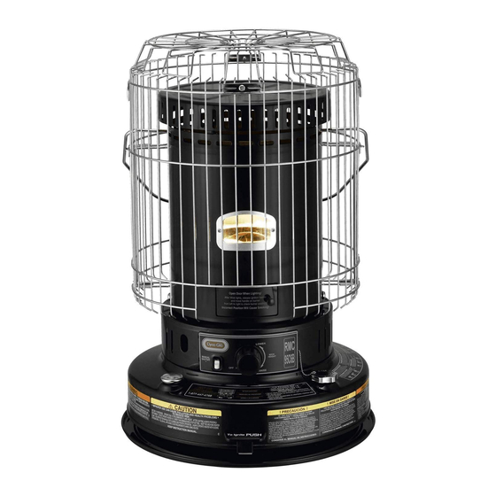
Dyna-Glo RMC- 95C6B Manual del usuario - Página 12
Navegue en línea o descargue pdf Manual del usuario para Calentador Dyna-Glo RMC- 95C6B. Dyna-Glo RMC- 95C6B 18 páginas. Portable
kerosene-heater
También para Dyna-Glo RMC- 95C6B: Manual del usuario (18 páginas)

NEVER LEAVE THE HEATER
UNATTENDED WHILE BURNING!
15
.Turn the wick assembly upside down to replace the wick cover.
16
. Align the tabs on the wick cover with the four screw holes on the bottom of the assembly, as shown, and snap it
into place. Be certain of firm contact at all points.
17
. Be sure the rubber seal on tank is properly seated. <Fig. B>
Fig.A
18
. (1) Turn the wick adjustment knob to the fully raised position. (2) Pull lightly on the
skirt of the wick to remove any slack. (3) Press lightly to secure the skirt to the
retainer teeth on the wick cover. (4) You will need to hold the knob in the
clockwise position to keep the wick raised. <Fig. A>
WICK INSTALLATION TIP
** Lock the tip over switch (TOS) by inserting locking pliers or a clothes pin between the TOS plates, preventing
the weight from triggering the TOS mechanism as you install the new wick. Install the new wick in the raised
position. Remember to remove pliers or clothes pin before reassembling & lighting heater.
19
. (5) Replace the wick assembly on the heater with the wick raised. (6) The wick adjuster knob will need to be
positioned between the caution and warning labels. <Fig.C> (7) Replace two diagonally opposite wing nuts first.
(8) Then the remaining two. (9) Tighten each of the four wing nuts gradually until the wick assmbly is firmly in place.
20
. While your heater is disassembled, check the Automatic Safety Shutoff system. Remove the locking pliers or
clothes pin from the TOS mechanism if you used them to assist with the wick installation.
Trip the automatic shutoff system by nudging the pendulum.
Raise the wick by turning wick adjuster knob. Trip it again to make certain it is operating correctly.
21
. Turn the Wick Adjustment knob to test its operation. Be certain the Wick operates smoothly as the knob is
turned CLOCKWISE and COUNTER-CLOCKWISE.
22
. Test Ignition. Raise the Wick to its full height. The Ignition Plug should be within 3/64" to 5/64" (1 mm to 2 mm)
of the Wick when the Lever is pulled. (CAUTION : Do not touch the HOT, glowing ignitor!)
23
. Be sure to check that the wick is set at the correct height of 3/8" (10 mm)
24
. Remove Wick adjustment knob which you had temporarily replaced to test wick operation.
25
. Replace the cabinet base making certain to align the automatic safety shutoff system lever and the wick
adjustment shaft, which holds the knob, with the appropriate slots in the cabinet base.
Begin by aligning them and gently snap the cabinet base in place over the wick assembly.
26
. Replace the heater cabinet. Make certain the grill guard prongs are inserted securely into the proper holes
on the heater, and the front cabinet matches the front of the heater.
27
. Fasten the cabinet to the heater with the two screws.
28
. Replace the wick adjustment knob. To be certain it is properly positioned on the wick adjustment shaft,
raise the wick to its full height.
F
g i
B .
11
F
g i
C .
