Active Silicon AS-CIB-3GSDI-002-EVAL-B Manual de inicio rápido - Página 5
Navegue en línea o descargue pdf Manual de inicio rápido para Accesorios para cámaras Active Silicon AS-CIB-3GSDI-002-EVAL-B. Active Silicon AS-CIB-3GSDI-002-EVAL-B 10 páginas. Evaluation kit for harrier af-zoom sdi cameras
También para Active Silicon AS-CIB-3GSDI-002-EVAL-B: Manual de inicio rápido (8 páginas)

Setting up the System
To get the Harrier AF-Zoom SDI camera running, follow the instructions below (also see figure 8):
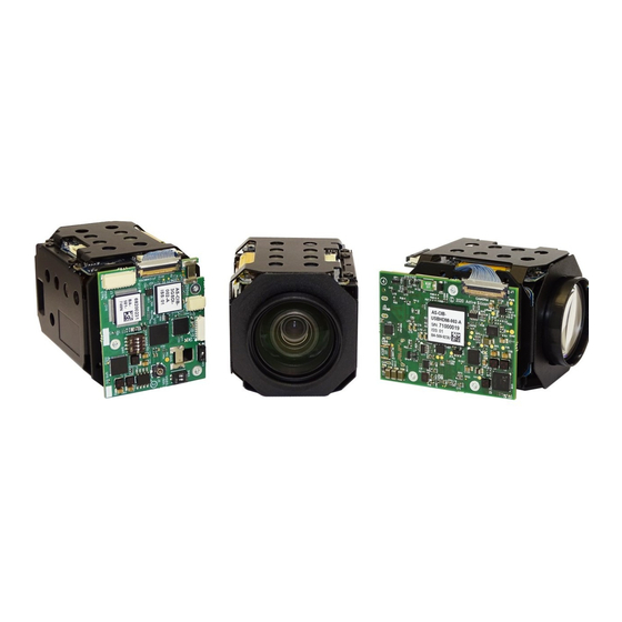
1. Connect the 9-way 1.0mm pitch FFC connector on the camera (J202 / J205 shown below) to
the FFC breakout board using the 9-way 1.0mm pitch FFC cable.
J202
2. Connect the 10-way wire cable from the FFC breakout board to the Harrier Evaluation Board
I/O connector (J103). See figure 8.
3. For capturing analog camera output connect the J301 (Analog) BNC socket on the Harrier
Evaluation Board to an analog monitor/display using a suitable coaxial cable.
4. For EX-SDI/HD-SDI camera output, connect the MMCX-BNC adaptor cable to the MMCX
socket on the top of the camera. Using a 75 Ohm 3G-SDI/HD-SDI digital video quality BNC
cable, connect the BNC end of the adapter to an EX-SDI/HD-SDI capable monitor/display.
5. For serial communications with the camera, use the mini USB–USB Type-A cable to
connect the mini USB socket (CN1) on the Harrier Evaluation Board to a PC. The USB PWR
LED should light up indicating a live connection to the PC. Three serial interfaces will appear
as COM ports on the PC and be accessible to PC software, one of these will be the serial
connection to the camera and can be used with the
or other serial control applications, to communicate with the camera. The HarrierControl
application can be downloaded at
6. Set the Harrier Evaluation Board power switch (SW302) to OFF (left viewed from above).
7. Connect the power supply barrel connector to the Harrier Evaluation Board power input
connector (J306).
8. Plug in the power supply and switch ON the Harrier Evaluation Board power switch (SW302).
The PWR ON should light up.
9. The camera will make audible mechanical noises as it goes through its power up sequence
and after a short time the video outputs will start working.
Note: the camera will power up in the last video mode used, some monitors cannot display
all the modes supported by the camera (notably 1080p30). If you have no visible SDI output
use the HarrierControl application to check/change the EX-SDI/HD-SDI video output mode
set on the camera to ensure that the camera output can be displayed on the SDI monitor.
10. If an analog monitor is connected to the Harrier Evaluation Board, and the camera analog
output is enabled you will see the camera output on the analog monitor.
11. If the EX-SDI/HD-SDI output is connected you will see the camera output on the
EX-SDI/HD-SDI monitor/display.
March 2022
HARRIER AF-ZOOM SDI CAMERAS
J205
HarrierControl
www.activesilicon.com
QUICK START GUIDE
Version 1.0.1 - March 2022
command line software,
from the
Software
page.
Page 5 of 10
