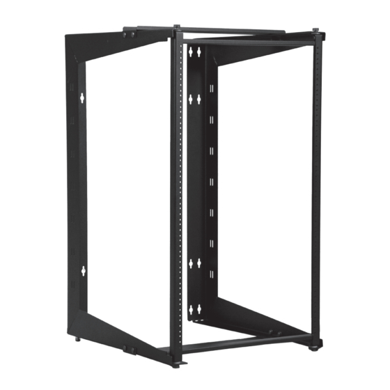
Great Lakes GL24SRD Manual de instrucciones de instalación - Página 6
Navegue en línea o descargue pdf Manual de instrucciones de instalación para Bastidores y soportes Great Lakes GL24SRD. Great Lakes GL24SRD 8 páginas. 19" eia srd swing rack
También para Great Lakes GL24SRD: Manual de instrucciones de instalación (12 páginas)

POWER
When using PDUs, each PDU should be connected to a committedbranch
circuit that is rated for the continuous load of all the equipment connected.
When not using a PDU, each piece of equipment should be connected to a
dedicated branch circuit.
PROTECTIVE EARTHING/GROUNDING
A main protective earthing stud is provided.
WARNING: To avoid injury to persons or loss of life, ground each SRD Swing
Rack individually to the dedicated branch circuit earthing ground
CONNECTING MAIN PROTECTIVE EARTHING STUD TO THE
DEDICATE D BRANCH CIRCUIT EARTHING GROUND CONDUCTOR
Connect the dedicated branch circuit earthing ground conductor to the main
protective earthing stud located on the support frame using a listed ring or
closed-loop terminal.
When installing a Great Lakes Swing Rack or Wall Mount to materials such
as wood, cinder block, concrete, etc., please consider the load capacity within
the swing rack or wall mount structure, and be certain to check with local
authorities to determine the appropriate hardware requirements for these
conditions. Because wall compositions may vary at different installation
sites, Great Lakes cannot warrant the fitness or suitability of any installation
instructions or installation hardware it may provide for swing rack or wall
mount enclosures. Great Lakes hereby DISCLAIMS ALL WARRANTIES,
EXPRESS AND IMPLIED, INCLUDING THE IMPLIED WARRANTIES OF
MERCHANTABILITY AND FITNESS FOR A PARTICULAR PURPOSE,
REGARDING THE SUFFICIENCY, FITNESS OR SUITABILITY OF ANY
INSTALLATION INSTRUCTIONS OR INSTALLATION HARDWARE GREAT
LAKES MAY PROVIDE FOR SWING RACKS AND WALL-MOUNTED
ENCLOSURES. Great Lakes recommends that an experienced maintenance
and/or technical person be consulted regarding the proper wall-mounting
hardware and procedures to be used for the anticipated load capacity of the
swing rack or wall mounted enclosure.
Product specifications are subject to change without prior notice.
6
