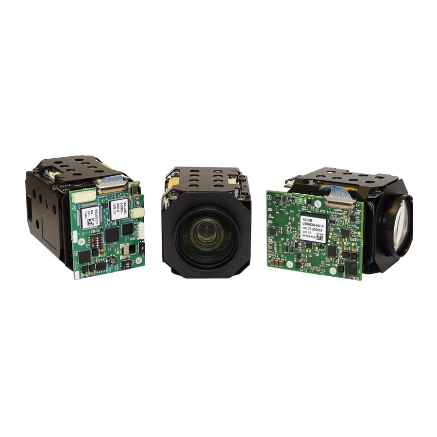
Active Silicon HARRIER Manual de inicio rápido - Página 6
Navegue en línea o descargue pdf Manual de inicio rápido para Equipos de grabación Active Silicon HARRIER. Active Silicon HARRIER 15 páginas. Usb/hdmi camera interface board

control or by using a VISCA serial command, followed by a camera reset (there is also the
camera hard reset in the extended VISCA commands which will also serve this purpose).
2) Due to the high data bandwidth required, these video modes (above 1080p30) require the
camera to be set to dual LVDS mode. Other modes (1080p30 and below) require the camera to
be set to single LVDS mode. When using VISCA commands to change camera video mode the
LVDS mode must also be set correctly, otherwise there will be no video output from the camera.
See your camera documentation for more information on VISCA commands and setting LVDS
modes.
Note: the MP2030M-GS camera does not support Dual LVDS mode or 1080p60/50 output.
3) The MP2030M-GS camera only supports these video modes.
4) The DIP switches to select the video format are only read on power-up. Therefore, to
change mode using the DIP switches, power down the camera, set the switches and then power
up the camera. DIP switches will only be effective for the operating modes supported by the
camera currently in use.
Harrier Evaluation Board Overview
Figure 9. Harrier Evaluation Board diagram
The Harrier Evaluation Board connects to the camera interface board using the supplied cable kit.
•
JTAG (J104)
•
I/O (J102)
•
Power/control, RS-232 (J103) - 10-way cable (connects to J3).
The board is powered by the 12V power supply via a barrel connector (J306). This supply is also
used as a power supply for the camera and is connected to the camera via the Power Switch
March 2021
HARRIER USB/HDMI CAMERA INTERFACE BOARD
- white 8-way cable (connects to J4, not required in normal use).
- 4-way cable (connects to J2).
QUICK START GUIDE
Version 1.7 – March 2021
Page 6 of 14
