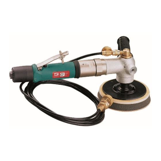
Dynabrade 51476 Manual del usuario - Página 4
Navegue en línea o descargue pdf Manual del usuario para Sander Dynabrade 51476. Dynabrade 51476 4 páginas. Wet sander/polisher

Disassembly/Assembly Instructions - Sander / Polisher (continued)
Motor Housing Reassembly:
1. Insert 01247 Regulator with o-rings and valve stem, place into motor housing. Secure with 95558 Retaining Ring.
2. Secure valve body in padded vise with inlet facing upwards. Insert 01464 Seal.
3. Line up hole in valve stem with hole in housing (looking past brass bushing). Insert 01472 Tip Valve so that the metal pin passes through the hole in the
valve stem. Install 01468 Spring (small end towards tip valve).
4. Assemble felt muffler and place in 94522 Muffler Cap. Install 94521 Muffler Base onto muffler cap.
5. Install 94538 O-Ring into groove on muffler base. Place 95375 O-Ring and 94526 Spacer into recessed area of muffler cap.
6. Slip 94523 Inlet Adapter through muffler assembly and install 95711 Retainer Ring into groove on inlet adapter.
7. Install 01564 Air Control Ring into valve body housing.
8. Apply #567 Loctite Pipe Sealant to threads of 94523 Inlet Adapter and install entire muffler assembly onto valve body (torque 23.0 N•m/200 in-lbs.).
9. Replace air fitting. Secure inlet adapter with a wrench before tightening air fitting. Install throttle lever and 01017 Pin.
Right-Angle Housing and Spindle Reassembly:
1. Secure 50985 Pinion Shaft in padded vise with key slot end up. Install 02552 Bearing onto pinion shaft.
2. Press pinion gear onto pinion shaft with 50435 Key in key slot. replace 95939 Retaining Ring.
3. Secure pinion in padded vise and install 50986 Spacer, 01266 Bearing and 53551 Coupling Nut.
4. The 50986 Spacer must fit snug between the two 01266 Bearings (shim required to achieve a snug fit).
5. Apply #271 Loctite adhesive to spindle thread and install 53551 Coupling Nut (torque 17 N•m/150 in-lbs.).
6. Install 96235 Shell Bearing into angle housing and insert pinion/shaft assembly.
7. Apply #567 Loctite to angle housing and install 50987 Lock Ring (left-hand thread, 44mm wrench flats).
8. Insert 50951 Coupling over 53551 Coupling Nut.
9. Install 50987 Lock Ring and angle housing sub-assembly onto 50970 Gear Casing. Take care in the aligning of the two male hex adapters to the 50951
Coupling (torque 45 N•m/400 in-lbs.).
10. Press 50887 Bearing and bevel gear onto spindle assembly.
11. Secure angle housing with drive spindle cavity facing upward and install well lubricated 02048 Wick (wick must be completely saturated with 95848 Gear
Oil before installation). Note: Do not contaminate wick with any other oil or grease product.
12. Insert spindle assembly and check for gear alignment and backlash. Install shims as required (Minimum backlash is recommended for maximum gear life.
Make sure there is clearance throughout 360° revolution.).
13. Install 50963 Retainer with 50899 Shaft seal in place (left-hand thread), torque 34 N•m/300 in-lbs.
Tool Assembly is complete. Please allow 30 minutes for adhesives to cure before operating tool.
Important: Motor should now be tested for proper operation at 90 PSI. If motor does not operate properly or operates at a higher RPM than marked on the
tool, the tool should be serviced to correct the cause before use. Before operating, place 2-3 drops of Dynabrade Air Lube (P/N 95842) directly into air inlet
with throttle lever depressed. Operate tool for 30 seconds to determine if tool is operating properly and to allow lubricating oils to properly penetrate motor
Loctite® is a registered trademark of Loctite Corp.
96178 Motor Tune-Up Kit
•
Includes assorted parts to help
maintain motor in tip-top shape.
Visit our new Web Site at http://www.dynabrade.com
DYNABRADE, INC., 8989 Sheridan Drive • Clarence, NY 14031-1490 • Phone: (716) 631-0100 • Fax: 716-631-2073 • International Fax: 716-631-2524
DYNABRADE EUROPE S.àr.l.,
© DYNABRADE, INC., 1998
Accessories
Zone Artisanale • L-5485 Wormeldange—Haut, Luxembourg • Telephone: 352 76 84 94 • Fax: 352 76 84 95
®
DYNABRADE
PRINTED IN USA
