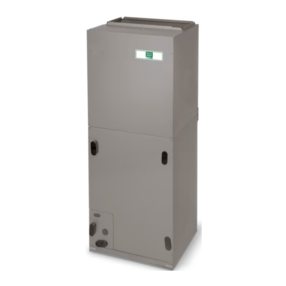
Day and Night TCH6 Manual de instrucciones de instalación - Página 8
Navegue en línea o descargue pdf Manual de instrucciones de instalación para Bomba de calor Day and Night TCH6. Day and Night TCH6 16 páginas. R?410a two?stage split system heat pumps

INSTALLATION INSTRUCTIONS
Replace stem caps after system is opened to
refrigerant flow. Replace caps finger−tight and tighten
with wrench an additional 1/12 turn
3. Close electrical disconnects to energize system.
4. Set room thermostat or Observer Wall Control at
desired temperature. Be sure set point is below indoor
ambient temperature.
5. Set room thermostat to HEAT or COOL and fan control
to ON or AUTO mode, as desired. Operate unit for 15
minutes. Check system refrigerant charge.
Observer Communicating Wall Control
Figure 10
Four−Wire Connection Diagram
Observer
Communicating
Wall Control
Green
DX+
Yellow
DX−
White
C
Red
R
S1
Optional Remote
Room Sensor
S2
Humidifier
Connection
NOTE: Wiring must conform to NEC or local codes.
NOTE: For standard thermidistat or thermostat wiring, see
Installation Instructions for those products.
FVM Fan Coil Wiring With
Figure 11
Two−Stage Heat Pump
Indoor Control
RVS Cooling
O/W2
Heat/Cool
Y1/W2
Stage 1
W/W1
Heat Stage 3
Heat/Cool
Y/Y2
Stage 2
Fan
G
24 VAC Hot
R
Dehumidify
DHUM
24 VAC Comm
C
HUM
Humidify
RVS Heating
B
S1
Outdoor
S2
8
Communicating
Variable Speed
Two-Stage
Furnace/Fan Coil
Heat Pump
Green
DX+
DX+
Yellow
DX−
DX−
C
C
R
HUM
COM
Two-Stage Heat Pump
Fan Coil
O
O
Y1
Y1
W1
W1
Remove J2 Jumper
For Heat Staging
W2
Y/Y2
Y2
G
R
H
C
C
Humidifier
(24 VAC)
Outdoor
Sensor
Specifications subject to change without notice.
Variable Speed Furnace with
Figure 12
Two−Stage Heat Pump (Dual Fuel)
Variable Speed
ICP Thermostat
W2
Y1
W1
Y2
G
R
H
C
L
O/B
OUTDOOR
OD
SENSOR
GND
Non−Communicating Indoor Unit with
Figure 13
Observer Communicating Wall Control
Wall
Control
DX+
R
C
DX-
C
R
W2
Y1
G
Y/Y2
Non-Communicating
Indoor
Note: This installation requires the daugh
ter board accessory, NAXA00101DB.
Note: This installation does not allow for
communicating feature functionality.
Check Charge
Two−stage equipment should be charged in high−stage
compressor operation only.
Factory charge amount and desired subcooling are shown
on unit rating plate. Charging method is shown on information
plate inside unit. To properly check or adjust charge,
conditions must be favorable for subcooling charging.
Favorable conditions exist when the outdoor temperature is
between 70_F and 100_F (21.11_C and 37.78_C), and the
indoor temperature is between 70_F and 80_F (21.11_C and
26.67_C). Follow the procedure below:
R−410A Split System Heat Pumps
Two-Stage
Heat Pump
Furnace
W2
Y1
Y1
W/W1
W1
Y/Y2
Y2
G
R
DHUM
COM
C
HUM
O
NAXA00101DB
Green
DX+
Red
R
White
C
Yellow
DX-
Communicating
Outdoor
C
C
R
W2
W1
Y1
Y1
G
Y2
Y2
O
O
OAT
Sensor
OAT
428 01 1703 01
